Do you have a question about the ASA Electronics Voyager VOM719WP and is the answer not in the manual?
Congratulations and encouragement to read the manual for optimal use and years of operation.
Covers crucial warnings on power connection, installation location laws, tampering, and depth perception.
Guidelines on moisture resistance (IP66) and proper cleaning methods to maintain the unit.
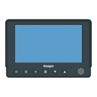
Instructions on how to turn the monitor unit on and off.
Procedure for switching between camera inputs and display modes.
How to adjust the screen brightness for day and night viewing.
Guidance on entering and operating the monitor's main menu.
Using UP/DOWN buttons to adjust brightness, contrast, color, tint, and volume.
Explanation of wire colors and pin functions for connections.
Steps for choosing locations, routing cables, and performing initial checks.
Connecting rear cameras for monitoring while backing up.
Connecting side cameras for lane changes or blind spot monitoring.
Detailed technical data for the monitor's LCD screen, including size, brightness, and view angle.
Key operating specifications such as voltage range, temperature, humidity, and current draw.
| Resolution | 800 x 480 |
|---|---|
| Power Supply | 12V DC |
| Contrast Ratio | 500:1 |
| Response Time | 30 ms |
| Power Consumption | 6W |
| Aspect Ratio | 16:9 |
| Screen Size | 7 inches |
| Brightness | 400 cd/m^2 |