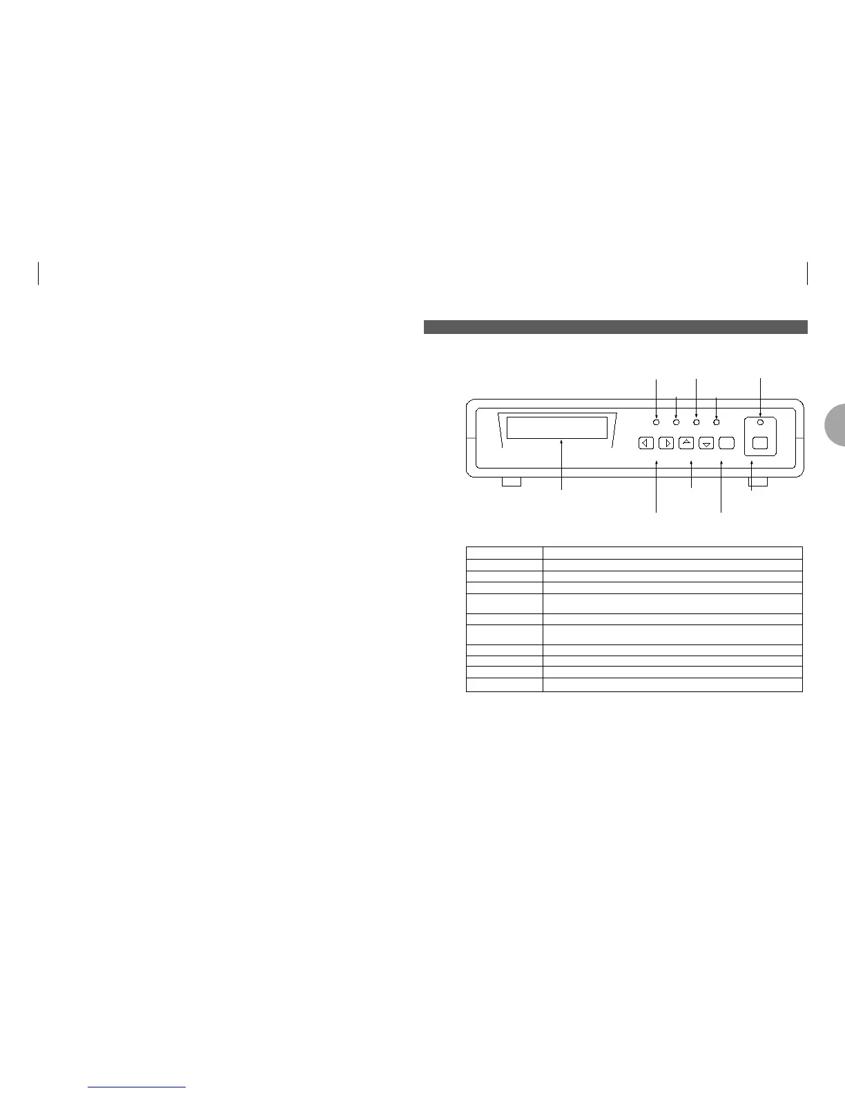
EasyManuals Logo

ASCOM AM 64/128EA User Manual

ASCOM AM 64/128EA
32 pages
To Next Page IconTo Next Page
To Previous Page IconTo Previous Page
Page #8 background imageLoading...
Page #8 background image
ASCOM USER GUIDE
High Speed Base Band Modems
13
3.1 FRONT PANEL
Item Function
LCD Liquid Crystal Display. Modem displays menu system here.
Power LED Green LED is lit when unit is powered.
Fault LED Red LED is lit when unit is not in synchronisation (sync).
Test LED Red LED is lit when a loop is applied to modem, the modem is applying a
remote loop or the unit is running a data test.
Receive data LED Amber LED indicates the received data status of the transmission line.
Program LED Amber LED is lit when new configuration settings have been made but
not committed to memory.
Menu Select Buttons Right and Left arrow buttons scrolls menus in the LCD display.
Item Scroll Buttons Up and Down arrow buttons scrolls menu items on the LCD display.
Item Select Button Selects Item displayed on LCD display.
Program Button Stores changes made in configuration to memory.
MENU SCROLL SELECT PROG
POWER FAULT TEST RXD
ascom
AM-64/512A
Liquid Crystal
Display
Program
Buttons
Menu Select
Buttons
Item Scroll
Buttons
Item Select
Buttons
Power LED
Fault LED
Test LED
Receive
Data LED
Program LED
3 UNIT FEATURES
3
12 ASCOM USER GUIDE
High Speed Base Band Modems

Table of Contents

Questions and Answers:

Question and Answer IconNeed help?

Do you have a question about the ASCOM AM 64/128EA and is the answer not in the manual?

ASCOM AM 64/128EA Specifications

General IconGeneral
BrandASCOM
ModelAM 64/128EA
CategoryModem
LanguageEnglish