TD 92022EN
3 July 2013 / Ver. G
Installation Guide
H/U952T Terminal Transmitter
11
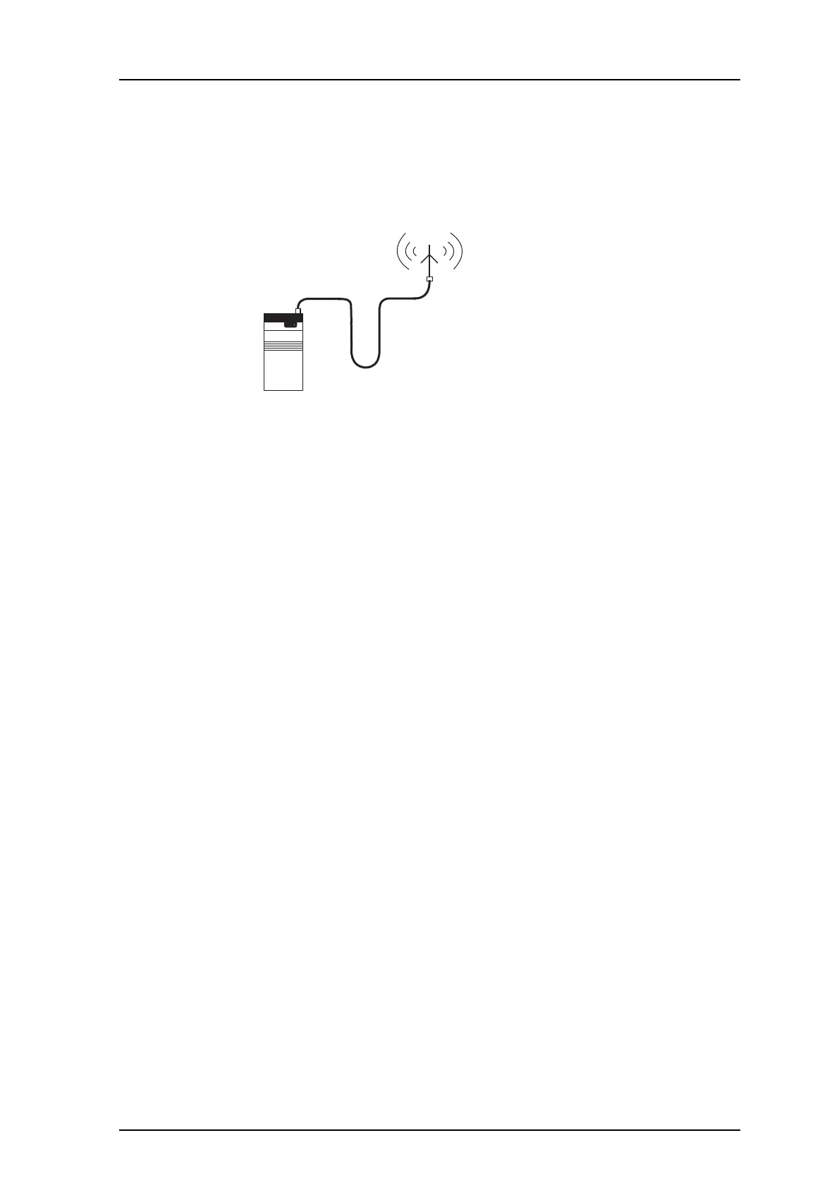
3.8 Coax Connection to Antenna
• Connect the antenna coax to the antenna output connector located at the upper right of
the Terminal Transmitter.
• To prevent water from running along the antenna cable and entering the Terminal
Transmitter
, let the cable form a loop downwards.
Transmitter
For assembly of the coax connector to the cable, see Appendix B.
When an outdoor antenna is used the screen of the antenna
cable may be connected to
protective earth. If there is more than one ground connection in the system it will generate a
ground loop. To avoid a ground loop, the antenna cable must be isolated from other
grounding points.
The following options are possible:
For HF: Use Antenna Transformer MAT-50 between the antenna and the Terminal
Tra
nsmitter.
For UHF: Insert isolation on the D-bus between the Central Unit an
d the Terminal
Transmitter. The speech and FL bus is already isolated by transformers. There are two
options:
1 T938D Data Modem. These are used in pairs and cause delay.
For more information see the Sys
t
em In
stallation document, chapter With Modem to
Transmitters. See also Installation Guide, Data Modem T938D, TD 90907GB.
2 T938BC2 Bus Converter. Isolation by an opto coupler. T938BC2 has two channels.
Only one is used
.
See Installation Guide, Bus Converter T938BC2, TD
90925GB.
IMPORTANT: The T938BC2 may be placed either at the Terminal Transmitter or at the
Central Unit position. The Central Unit position is recom
mended, since than
one channel may be used for one transmitter and the other channel for
another transmitter.
 Loading...

