This document is an Operations Manual for the ASEA Power Systems AC36Q-1, AC36Q-3, AC45Q-1, and AC45Q-3 Single and Three Phase Yacht Power Converters. It covers installation, operation, and preventative maintenance for these models.
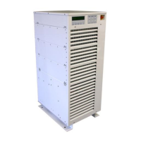
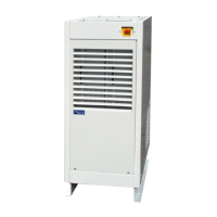
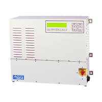
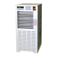
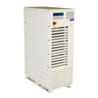
The AC36Q and AC45Q series are high-performance Yacht Power Converters designed for single or three-phase input service with a frequency between 40-70 Hertz and a voltage between 170-520VAC. The converter can auto-configure for the applied power form. The output power form is programmed at the factory for the power form, voltage, and frequency required by the yacht. Dual-conversion technology is employed, where the shore power is isolated by transformers, converted to DC by a Power Factor Correction (PFC) power supply, and then inverted back to the required AC form. The system consists of a control module (upper), three power modules (middle), and a transformer module (bottom). All system components are packaged in drip-proof, dust-resistant, aluminum chassis. Major components are internally modular, allowing simple exchange in the event of failure. Maintenance and service are performed through top access to the upper control module, exchange of power modules, and front/top access to the transformer module. Fan speed control is provided, with internal cooling fans running at full RPM when the converter is at full load and minimal speed while unloaded. System operation is managed through two basic operators: a safety disconnect on the front of the enclosure for securing input service during periods of disuse, and a membrane switch group in the control console—SHORE POWER, CONVERTER POWER, and SHIP’S POWER—to provide normal operation of the system. Each switch group contains an ON and OFF switch with associated LED indicators. The basic function of power conversion, each system provides the user with a sophisticated power analysis and monitoring capability. All parameters for input and output power, along with operations and status information, are available on the front panel display console. Various displays are selected through a long-life, sealed membrane switch panel.
Important Technical Specifications:
- Input Power Form: Single or Three Phase
- Input Voltage Range: 170-520 VAC
- Input Frequency Range: 40-70 Hertz
- Input Current, Max. Single Phase: 150 ARMS (AC36Q-1, -3), 187 ARMS (AC45Q-1, -3)
- Input Current, Max. Three Phase: 100 ARMS (AC36Q-1, -3), 125 ARMS (AC45Q-1, -3)
- Input Current, Soft Start, Max.: 42 ARMS (both models)
- Input Current Distortion: <5% THD @ rated load
- Input Power Factor: >0.99 @ rated load
Output Service:
- Output Power Rating: 36kVA @ 0.85 p.f. (AC36Q-1, -3), 45kVA @ 0.85 p.f. (AC45Q-1, -3)
- Output Power Form: Single Phase (220, 230, or 240VRMS), Split Phase (120/240VRMS), or Three Phase (120/208, 127/220, 220/380, 230/400, 240/416, or 254/440VRMS). Minor variations in voltage levels can be accommodated.
- Output Frequency: 50 or 60 Hertz
- Output Frequency Accuracy: 0.01%
- Output Voltage Distortion: < 1.5% THD
- Output Voltage Line Regulation: 0.50%
- Output Voltage Load Regulation: 1.0%
- Output Voltage Response Time: 0.20 msec.
- Output Current, Continuous:
- AC36Q-1: 164ARMS/Ø (220VRMS), 157ARMS/Ø (230VRMS), 150ARMS/Ø (240VRMS), 150ARMS/Ø (120/240VRMS)
- AC45Q-1: 205ARMS/Ø (220VRMS), 196ARMS/Ø (230VRMS), 187ARMS/Ø (240VRMS), 187ARMS/Ø (120/240VRMS)
- AC36Q-3: 100ARMS/Ø (120/208VRMS), 95ARMS/Ø (127/220VRMS), 56ARMS/Ø (220/380VRMS), 52ARMS/Ø (230/400VRMS), 50ARMS/Ø (240/416VRMS), 47ARMS/Ø (254/440VRMS)
- AC45Q-3: 125ARMS/Ø (120/208VRMS), 118ARMS/Ø (127/220VRMS), 68ARMS/Ø (220/380VRMS), 65ARMS/Ø (230/400VRMS), 63ARMS/Ø (240/416VRMS), 59ARMS/Ø (254/440VRMS)
- Output Current, Peak: 400% of cont. rating
- Output Current, Surge: 250% of cont. rating
- Conversion Efficiency: 91% @ rated load
Physical Specifications:
- Height: 47.1" / 120cm
- Width, Enclosure: 19.2" / 48.8cm
- Depth: 25.3" / 64.3cm
- Weight: 680lbs / 308kg
- Environmental:
- Ambient Temperature Range: 0-50°C non-condensing
- Air Exchange Rate: 1,300 CFM (ft³/min) / 2,209 m³/hour
- Thermal Load: Approximately 10,330 BTU/Hr (AC36Q) and 12,915 BTU/Hr (AC45Q) at maximum continuous load.
Usage Features:
- Parallel Operation: Each converter is capable of being paralleled for higher power applications.
- AC36Q paralleled: AC75Q-1/2 (75kVA 1 Phase), AC75Q-3/2 (75kVA 3 Phase)
- AC45Q paralleled: AC90Q-1/2 (90kVA 1 Phase), AC90Q-3/2 (90kVA 3 Phase)
- Input/Output Connections: Compression type terminal blocks for #6 AWG to 250MCM wires.
- Grounding: The converter equipment safety ground must be connected to the ship's hull or common ground point via a 3/8-16" stud. The converter isolates the output power from an isolation transformer. The installer must re-establish the ground reference for the equipment at the time of installation. The neutral and the equipment safety ground must be connected per the appropriate class standard.
- Multi-Cabinet Connections: Multi-cabinet systems are operated from the Master's control panel. An internal paralleling cable assembly (P/N 604650) is shipped pre-installed in Master and Slave cabinets. A paralleling cable assembly (P/N 603150) is shipped pre-installed in the Slave cabinet and coiled at the base of the cabinet near the Input and Output connection terminal blocks. This cable connects to the Master cabinet's parallel port.
- Seamless Transfer Option: Allows for seamless transfer between generator and converter power. The system matches the generator in voltage, frequency, and phase, briefly operating in parallel before opening the generator circuit breaker.
- Auto-Restart Feature: Automatically routes power from the dock to the ship's power bus. Front panel controls allow auto-restart to be enabled or disabled. Fault tolerant to guarantee safe operation. Validates shore power before restart. Handles repeated power failures without operator intervention.
- Remote Communication: The converter can be controlled remotely and queried for alarm, electrical, and status data through its RS-232C port. An optional Modbus Option converts the default hardware protocol to RS-485. Supports SCPI and Modbus software protocols. Baud rates include 1200, 2400, 4800, 9600, 19200 (standard for ASEA Power Systems Touch Screens), and 38400.
- Load Management System: Provides comprehensive load management features.
- Shore Cord Alarm: Drives Voltage Droop and Automatic Transfer to Generator features. User selects a percentage (50-100%) at which to begin alarming. This feature can be enabled or disabled. The alarm drives a relay's normally open contact pair rated for 8A @ 250VAC or 5A @ 24VDC.
- Shore Cord Setup: User selects actual shore cord ampacity from a table of available international shore cord sizes. This causes the converter to display load level and alarm based on the true available shore cord energy.
- Voltage Droop: If the yacht's electrical system lacks a power management system, this feature can save up to 10% capacity by reducing converter output voltage up to 5% (1-5% range). Enabled/disabled by the user, it droops upon Shore Cord Alarm. A recovery time (default 30 minutes, adjustable 1-60 minutes) is provided.
- Automatic Transfer to Generator: The converter can automatically transfer to a generator (with Seamless Transfer Option) upon Shore Cord Alarm. This occurs after Voltage Droop, if both are enabled. A signal from the converter can start the selected generator. A programmable warm-up delay is available.
- Generator Frequency Analysis: Displays minimum and maximum generator frequency observed over lifetime.
- Converter Output Impedance Control: Allows adjustment of Nominal Impedance Duty Cycle (0-100%) to increase output voltage and compensate for line-drop losses in remote locations. Automatic Gain Control (AGC) must be disabled when using this function. Transfer Impedance is usually modified by factory-trained personnel.
- AGC Control: Compensates for changes in output voltage not corrected by hardware and software calibration. Should be disabled before calibrating hardware oscillator and current compensation pots.
- kW-Hour Meter and Maximum Power Level Display: Provides reference kW-hour meter to check marina billing. Displays kW-hours, run time, maximum level (percentage), and maximum power (kW). Data can be cleared. Useful for diagnosing converter shutdowns if Max. Level exceeds 110%.
- Converter Output Voltage Control: Allows user to increase or decrease converter output voltage (Vout) in 0.5-volt increments within a +/-5% range of the factory programmed voltage.
- Event Log: Monitors internal converter logic operation. Stores up to 1000 past events. Events can be viewed, tracked, and registered (enabled/disabled for logging).
Maintenance Features:
- Preventative Maintenance: Minimal preventative maintenance is required.
- Tighten electrical connections: Every 6 months. Frequency varies based on wire gauge, wire type, and applied vibration. Refer to licensed electrician or factory authorized technician.
- Calibration: Every year. May require additional calibration after battery replacement. Lack of calibration may result in a 5% decrease in metering and voltage programming accuracy. Refer to factory authorized technician.
- CPU Battery replacement: Every 3 years. May require greater frequency with elevated ambient temperature or extended periods of non-operation. Refer to factory authorized technician.
- Troubleshooting and Diagnostics:
- Common Problems: Provides a list of symptoms and possible causes/suggested actions for common operational difficulties (e.g., no display, no fan activity, failure to accept button presses, unexpected trips).
- Failure and Warning Messages: Displays various FAILURE or WARNING messages (e.g., D86 LVDC FAULT, INPUT_OVERLOAD, INV_X_OT, T1_OT). Messages can be cleared by pressing F1 and F2 simultaneously.
- Info Display: Provides messages describing the reason for SHORE POWER status (e.g., INPUT is ONLINE, BLACKOUT OR RED-EMERGENCY SWITCH, OVERLOAD SHUTDOWN).
- Status Words: Three STATUS WORDs (SW1, SW2, SW3) are provided in the STATUS WORD DISPLAY, containing information about internal logic levels in both binary and HEX format, to aid in system diagnostics.
- Gathering Data: If a problem occurs, users are advised to record FAULT/WARNING messages, INFO display contents, and STATUS WORDs before removing power and to have this information, along with model number, serial number, and software version, ready when contacting service.
- Software Tools: ASEA Power Systems offers downloadable software tools, including an EVENT LOG VIEWER, for analysis of the converter's event log.