EasyManua.ls Logo

Ashford TRADITIONAL SPINNING WHEEL User Manual

Ashford TRADITIONAL SPINNING WHEEL
18 pages
To Next Page IconTo Next Page
Page #1 background imageLoading...
Page #1 background image
Ashford Guarantee
Thank you for purchasing this Ashford product. In the unlikely event there is
any fault in manufacture, please contact the dealer you purchased it from. To
validate the guarantee, please go to www.ashford.co.nz/product-registration
or email us.
Ashford Handicrafts Limited
Factory and Showroom: 415 West Street
PO Box 474, Ashburton 7700 New Zealand
Telephone 64 3 308 9087
Email: sales@ashford.co.nz Internet: www.ashford.co.nz
INSTRUCTIONS
TRADITIONAL SPINNING WHEEL
TDSW-DDSW030920V1
SINGLE DRIVE
DOUBLE DRIVE
ASHFORD TRADITIONAL SPINNING WHEEL
SINGLE DRIVE
TDSW140519V13
ASHFORD TRADITIONAL SPINNING WHEEL
DOUBLE DRIVE
DDSW140519V11
Question and Answer IconNeed help?

Do you have a question about the Ashford TRADITIONAL SPINNING WHEEL and is the answer not in the manual?

Ashford TRADITIONAL SPINNING WHEEL Specifications

General IconGeneral
BrandAshford
ModelTRADITIONAL SPINNING WHEEL
CategoryWeaving Tools & Accessories
LanguageEnglish

Summary

Ashford Traditional Spinning Wheel Overview

Double Drive and Single Drive Models

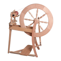
Visual introduction to the Double Drive and Single Drive traditional spinning wheel models.

Assembly Instructions: Preparation and Tools

Pre-Assembly Recommendations

Guidelines for reading instructions, preparing parts, and protecting surfaces before assembly.

Required Tools and Assembly Tips

Lists necessary tools and provides helpful hints for a smoother assembly process.

Further Information and Resources

Guidance on accessing online videos and relevant publications for additional support.

Hardware Components List

Core Spinning Wheel Construction

Frame and Treadle Assembly

Steps 1-3: Connecting side rails, legs, treadle rail, and treadle assembly with correct orientation.

Crankshaft and Wheel Installation

Steps 4-9: Lubricating components, attaching wheel support, installing crankshaft, hub pin, and conrod.

Single Drive Assembly Procedures

Flyer Unit and Maid Upright Setup

Steps 12-14: Attaching hooks, assembling the flyer unit, and securing maid uprights for single drive.

Brake Band and Drive Belt Attachment

Steps 15-17: Placing the bobbin and flyer, attaching the brake band, and configuring the drive belt.

Final Single Drive Adjustments and Ratios

Steps 18-21: Finalizing drive belt placement, aligning pulleys, and understanding single drive ratios.

Double Drive Assembly Procedures

Flyer Unit and Maid Upright Setup (Double Drive)

Steps 22-24: Attaching hooks, assembling the flyer unit, and securing maid uprights for double drive.

Brake Band and Drive Band Configuration (Double Drive)

Steps 25-27: Placing the bobbin and flyer, attaching the brake band, and configuring the drive band.

Final Double Drive Adjustments and Ratios

Steps 28-32: Finalizing drive belt placement, aligning pulleys, and understanding double drive ratios and bobbin lead.

Accessory Assembly: Lazy Kate

Lazy Kate Construction Details

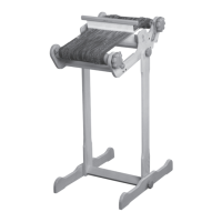
Assembling the Lazy Kate, ensuring countersunk holes face inwards on uprights.

Conrod Joint Pre-Assembly Note

Information regarding the factory pre-assembly of polyurethane conrod joints.

Related product manuals