6
© 2021 United States Stove Company
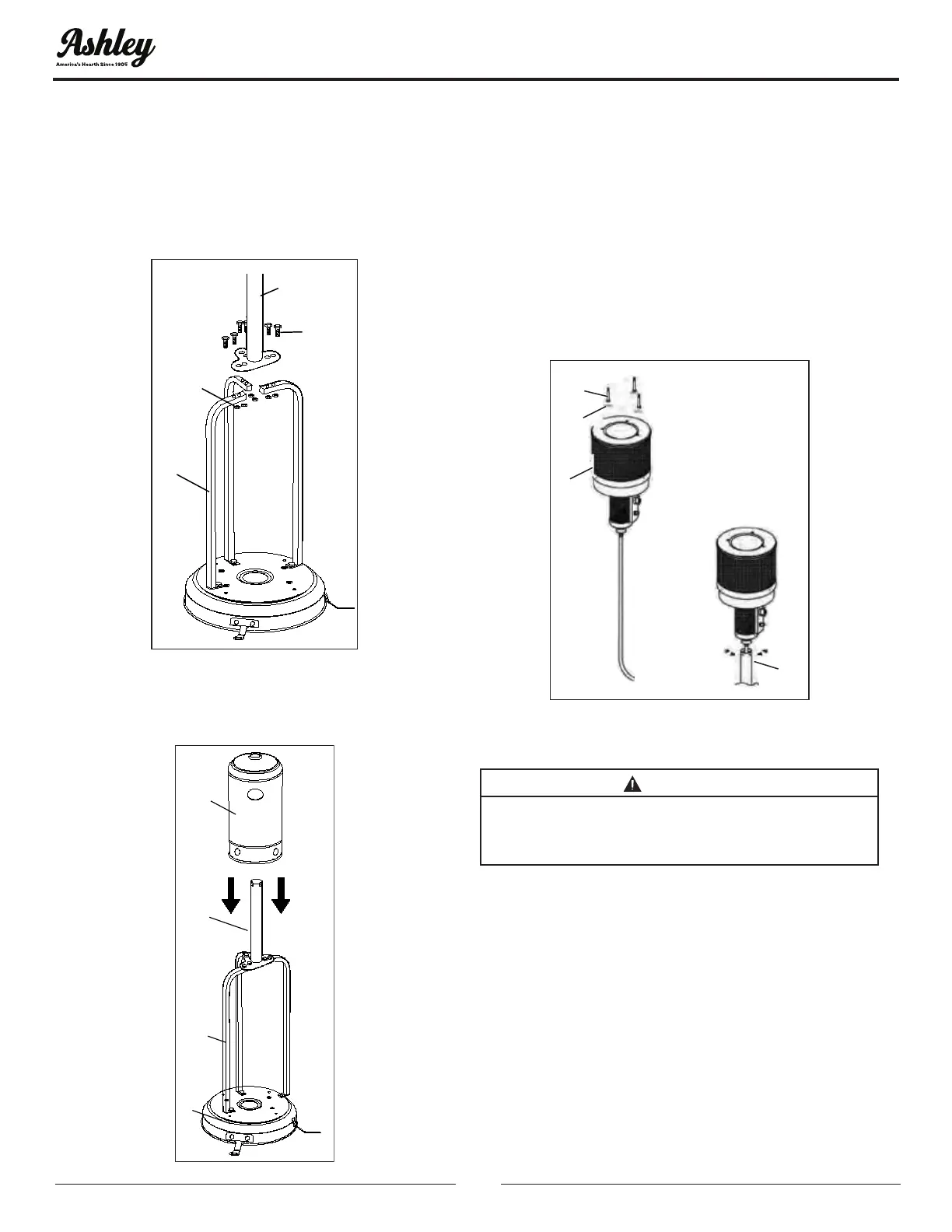
STEP 2
2-1. Put the post on the top of 3 tank housing
supports.
2-2. Use 6 M6 bolts (FF) and nuts (GG) to connect
the post to the 3 tank housing supports. Tighten
the bolts and nuts.
FF
F
D
GG
FF*6
GG*6
STEP 3
3-1. Place the tank housing (E) on the base (G).
E
D
F
G
STEP 4
4-1. Attach a reector stud (CC) and three washers
Ø8mm (JJ) to the top of the burner (C). Tighten the
reector stud.
4-2. Unscrew the four screws that are already
assembled on the burner assembly (C). Place the
burner assembly (C) into the top of the post (D) by
inserting the regulator into the post (D). Tightly
fasten the previously removed screws back into the
burner assembly (C) through the slots at the top of
the post (D).
CC
JJ
C
D
CC*3
JJ*3
STEP 5
WARNING:
REMOVE THE PLASTIC PROTECTIVE COATING
ON THE REFLECTOR PANEL AND CENTER THE
5-1. Attach the two reectors with 1 cross bolt M6*8
(BB) and 1 cap nut M6 (AA), repeat this step to install
the third reector.
5-2. Then attach and lock the reector plate and the
newly attached reector with 6 cross bolts M6*8
(BB) and 6 cap nuts M6 (AA).