5
ASSEMBLY
6
10
9
7
8
3
2
5
4
1
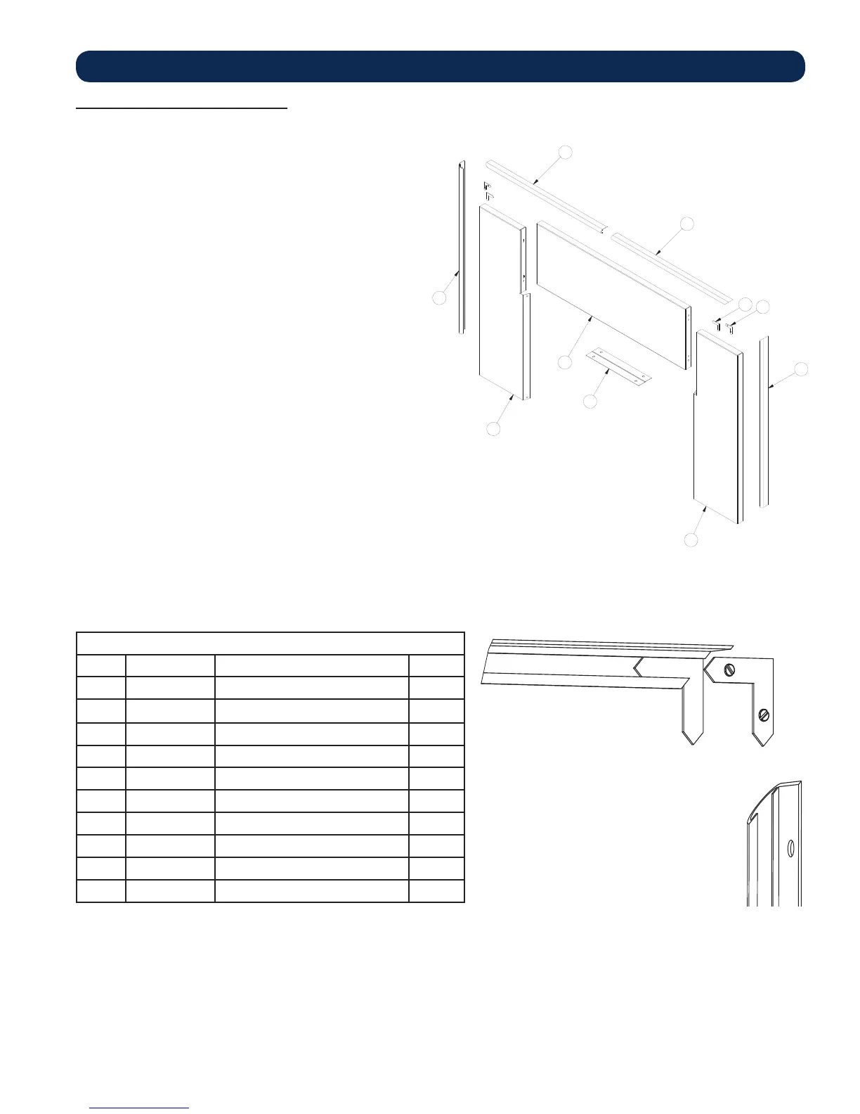
Kit Contents
Key Part Description Qty.
1 26414 Clamp, Top Trim 1
2 26735 Right Panel, Facade 1
3 26736 Left Panel, Facade 1
4 26734 Central Panel, Facade 1
5 892455-3 Trim, Facade Side-Left 1
6 891435-1 Trim, Facade Top-Left 1
7 891435-2 Trim, Facade Top-Right 1
8 892455-4 Trim, Facade Side-Right 1
9 444-1B-S-2 Corner Key W/ Screw 2
10 444-2 Blank Corner Key 2
INSERT KEYS BEHIND FLANGE OF TRIM AS
SHOWN. BLANK CORNER KEY MUST BE IN-
STALLED FIRST. INSERT SECOND KEY. ADJUST
TRIM AND TIGHTEN SET SCREWS.
ASSEMBLY INSTRUCTIONS
1. Position stove in fi replace. Align facade panels with fi replace
and top of stove. The panels should be fl at against the fi replace
and standing vertical.
Notes: The side facade pieces go behind the top
piece.
The facade must be installed before unit is set
into its fi nal position.
2. Mark the location of the facade panels along the top of the
stove with a pencil. The mark will be used to realign the panels
later.
3. Slide stove out of fi replace far enough to be able to work
behind facade panels.
4. Realign the fi rst side panel with the mark made previously.
5. Using the predrilled holes in the facade panel as a guide; mark
and drill holes for the self tapping screws used to mount the
facade panel. See illustration on right below.
Note: Align the mounting screws with the center of the
predrilled holes to allow for adjustment.
6. Repeat steps 4 and 5 for the other side panel.
7. Attach side panel trim as shown. See illustration on left below.
8. Attach top panel retainer with two self tapping screws.
9. Ensure venting is attached properly.
10. Align the top panel with the retainer and side panels
11. Attach top panel trim.
Note: Stove and facade panels should realign with fi replace to
allow the panels to be fl at against fi replace and standing
vertically.