MPS-Series – Installation Guide
U-0664-0174.doc – Issue: 07 complete, approved
Page 5 of 24
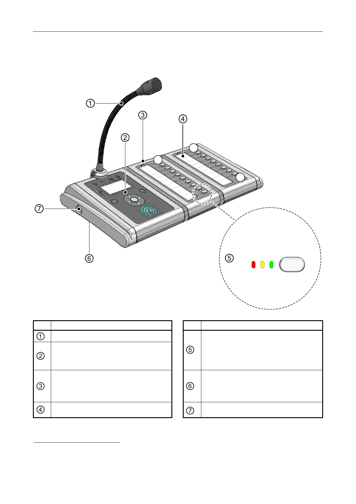
2 Controls and Indicators
BUTTON
oice Alarm (red)
Fault (yellow)
Select/Busy (green)
MPS20
(20-BUTTON MICROPHONE)
LEDs
EN54-16 MODE:
B01
B11
B20
FUNCTION BUTTON
(B01 TO B20)
Item
Description
Item
Description
Gooseneck microphone
Main user interface (see details below)
Function button
1
and indicators.
EN 54-16 indication mode
2
:
• Red LED = Voice Alarm
• Yellow LED = Fault
• Green LED = Select/Busy
MPX10 10-button Expansion Module
3
:
• MPS01: none fitted
• MPS10: one fitted
• MPS20: two fitted
Built-in loudspeaker (under the unit)
Function button identification label (under
plastic cover)
Emergency mode keyswitch
1
The available functions depend on the PA/VA system that hosts the microphone.
2
Refer to the application specific documentation for other indication modes.
3
Special variants are available to order, with more MPX10 button expansion modules and/or button module to the left of the gooseneck microphone and/or
to the right.