V400 – Installation Guide
U-0398-0607.doc – Issue: 03 complete, approved
Page 13 of 24
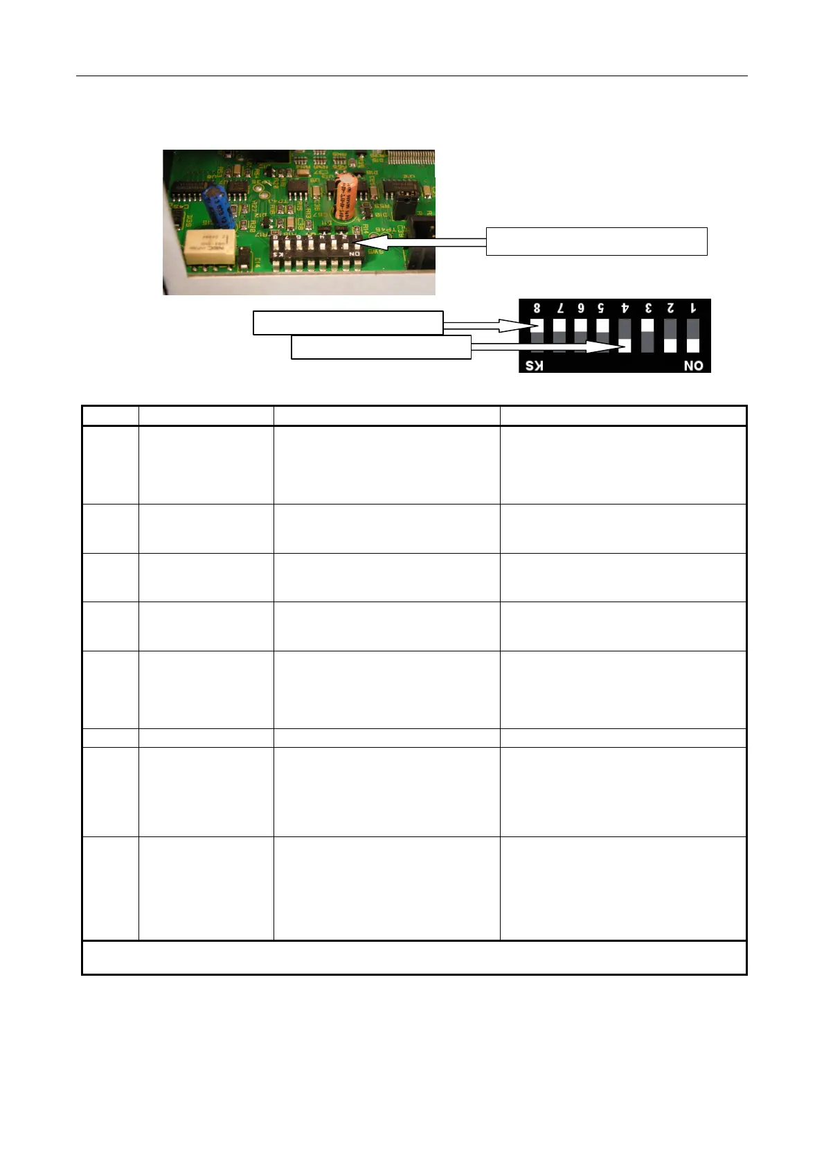
Figure 8 DIP Switch Selection
DIP switch position on the rear of V400
DIP switch in the “OFF”
osition
DIP switch in the “ON”
osition
SW No. Switch Name Function when ON Function when OFF
SW1
Deep Discharge
Disconnect
Amplifier mainframe will continue to draw
power from the batteries, even when the
battery voltage drops below 21 V.
Amplifier mainframe is automatically
switched off if the standby battery voltage
drops below 21 V.
This protects the battery from being
completely discharged.
SW2
Mains Fault Reporting
Enable
AC mains faults ARE reported. (1)
AC Mains faults ARE NOT reported.
Use only when the mainframe is being
supplied from batteries only.
SW3
Battery Fault Reporting
Enable
Battery supply faults ARE reported. (1)
Battery supply faults ARE NOT reported.
Use only when the mainframe is being
supplied from AC mains only (no batteries).
SW4
Aux Supply Fault
Reporting Enable
Aux supply faults ARE reported. (1)
Aux supply output faults ARE NOT reported.
Use only when the auxiliary DC supply output
is not being used to power other equipment.
SW5
CPU Fault Local
Latching Enable
Mainframe CPU faults are reported by
front panel LED latching ON.
Set to ON only if the mainframe is being
used 'stand-alone', and it is desired that
CPU reset causes LED to latch on.
Mainframe CPU faults not latched by the front
panel LED.
Set to OFF for all Voice Alarm applications
where the mainframes are integrated with a
VAR Router.
SW6 Not used Not used Not used
SW7
Remote Battery
Switching Enable
Batteries CAN be connected /
disconnected remotely (e.g. from a rack
master switch using the remote battery
on/off control input), instead of the
mainframe front panel battery disconnect
switch.)
Batteries CANNOT be connected /
disconnected remotely.
SW8
CAN Termination
Resistor In Circuit:
Set to OFF. This switch
should only be set ON if
an external CAN bus
termination resistor is
not used
An external CAN bus terminating resistor
IS NOT used.
An external CAN bus terminating resistor IS
used.
1) For full compliance with EN54-16, ISO 7240-16, BS 5839-8 and BS EN 60849, all power supplies should be monitored. This
switch should, therefore, be set to ON.
 Loading...