V400 – Installation Guide
U-0398-0607.doc – Issue: 03 complete, approved
Page 14 of 24
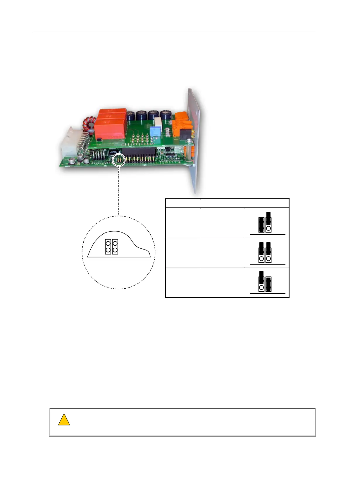
10. If the LSDDC Surveillance Card is used, then set the operation mode to single, dual or loop return
mode as required; see Figure 9.
Figure 9 Setting the LSDDC Operation Mode
Mode Setting
Single Circuit
LK9 fitted
LK10 not fitted
Dual Circuit
No links fitted
(Factory default)
Loop Return
LK9 not fitted
LK10 fitted
LK9
LK10
LK9
LK10
LK9
LK10
LK9
EDGE OF PCB
LK10
11. Insert the required interface cards into the rear of the V400 amplifier mainframe, ensuring it is in the
correct position to mate with its amplifier module and push it home; see Figure 10.
All empty slots must be covered with blanking panels (ASL P/N: RBLANK-V400).
Interface Cards compatible with the M100, M200 and M400 amplifier modules are:
• LSDDC: Dual DC Line Surveillance Interface Card
• SSINT: Standby Surveillance Interface Card
• NSINT: Non-Surveillance Interface Card
• LSIDC: DC Line Surveillance Interface Card
!
!
Install 4 x M3 (6 mm) Pozi Pan head fixing screws to bond each interface panel to the amplifier
mainframe chassis and fully tighten the screws. It is important to make sure the screws are fully
tightened to prevent dangerous voltages being present on the panel.
 Loading...