V400 – Installation Guide
U-0398-0607.doc – Issue: 03 complete, approved
Page 15 of 24
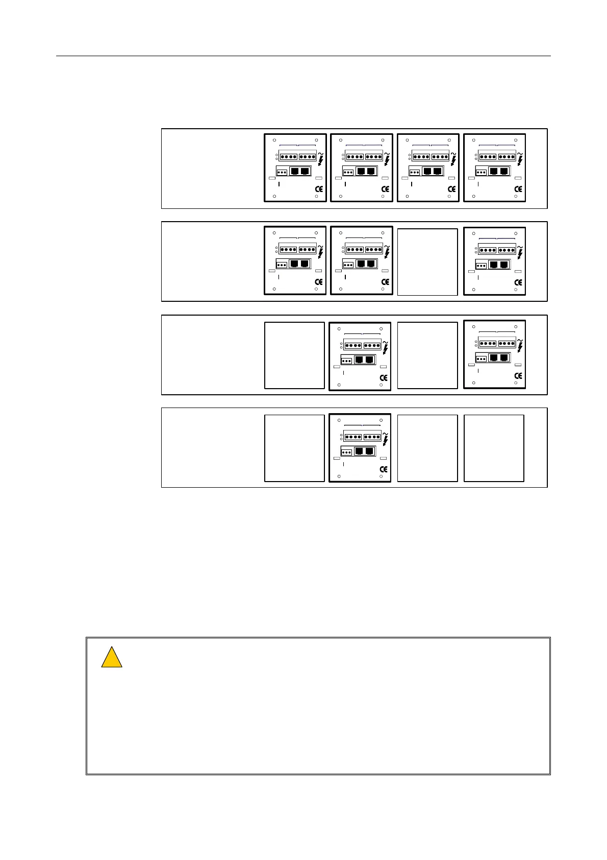
Figure 10 Interface Card Positioning Relative to Installed Amplifier Modules (Example with LSDDC)
1 x 400 W
BLANKBLANK BLANK
2 x 200 W
BLANKBLANK
2 x 100 W and
1 x 200 W
BLANK
4 x 100 W
Slot 4 Slot 3 Slot 2 Slot 1
(Rear view of V400 mainframe fitted with LSDDC Interface Cards as example.)
100V
-+-+ +-+-
LINE OUT STANDB Y IN
SURVEILLANCE INTERFACE
LSDDC
BA
A
B
FAULT
INPUT
...
-+
SCREEN
LOW LEVEL
ST ANDBY AN D
OVERRIDE
LINK
100V
-+-+ +-+-
LINE OUT STANDB Y IN
SURVEILLANCE INTERFACE
LSDDC
BA
A
B
FAULT
INPUT
...
-+
SCREEN
LOW LEVEL
ST ANDBY AN D
OVERRIDE
LINK
100V
-+-+ +-+-
LINE O UT STAND BY IN
SURVEILLANCE INTERFACE
LSDDC
BA
A
B
FAULT
INP UT
...
-+
SCREEN
LOW LEVEL
STAND BY AND
OVERRIDE
LINK
100V
-+-+ +-+-
LINE O UT STAND BY IN
SURVEILLANCE INTERFACE
LSDDC
BA
A
B
FAULT
INPUT
...
-+
SCREEN
LOW LEVEL
STAND BY AND
OVERRIDE
LINK
100V
-+-+ +-+-
LINE OUT STANDB Y IN
SURVEILLANCE INTERFACE
LSDDC
BA
A
B
FAULT
INPUT
...
-+
SCREEN
LOW LEVEL
ST ANDBY AN D
OVERRIDE
LINK
100V
-+-+ +-+-
LINE O UT STAND BY IN
SURVEILLANCE INTERFACE
LSDDC
BA
A
B
FAULT
INPUT
...
-+
SCREEN
LOW LEVEL
STAND BY AND
OVERRIDE
LINK
100V
-+-+ +-+-
LINE O UT STAND BY IN
SURVEILLANCE INTERFACE
LSDDC
BA
A
B
FAULT
INP UT
...
-+
SCREEN
LOW LEVEL
STAND BY AND
OVERRIDE
LINK
100V
-+-+ +-+-
LINE O UT STAND BY IN
SURVEILLANCE INTERFACE
LSDDC
BA
A
B
FAULT
INPUT
...
-+
SCREEN
LOW LEVEL
STAND BY AND
OVERRIDE
LINK
100V
-+-+ +-+-
LINE O UT STAND BY IN
SURVEILLANCE INTERFACE
LSDDC
BA
A
B
FAULT
INP UT
...
-+
SCREEN
LOW LEVEL
STAND BY AND
OVERRIDE
LINK
100V
-+-+ +-+-
LINE O UT STAND BY IN
SURVEILLANCE INTERFACE
LSDDC
BA
A
B
FAULT
INPUT
...
-+
SCREEN
LOW LEVEL
STAND BY AND
OVERRIDE
LINK
12. Connect the field wiring to the installed Interface Cards.
Please refer to Section “2 Connection” (page 18) for pinout details.
13. If AEL (Active End of Line Device) is used, then install the AEL unit referring to the AEL Installation
Guide.
14. Connect the AC mains power supply cable; see Figure 11.
!
!
1) Always ensure that the equipment is correctly earthed by connection to an AC mains
supply with a protective earthing connection.
2) Ensure power supply cabling is adequately rated for the unit’s operating current and is
protected against short circuit by a correctly rated fuse or circuit breaker.
3) Using too thin a cable can cause a safety hazard and will give excessive voltage drop and
operational failure.
4) Note that if the amplifiers are connected as a system which is permanently connected to
the mains, then an all-pole mains isolator with a separation of 3 mm in each pole shall be
incorporated in the electrical installation.
 Loading...