V400 – Installation Guide
U-0398-0607.doc – Issue: 03 complete, approved
Page 18 of 24
2 Connection
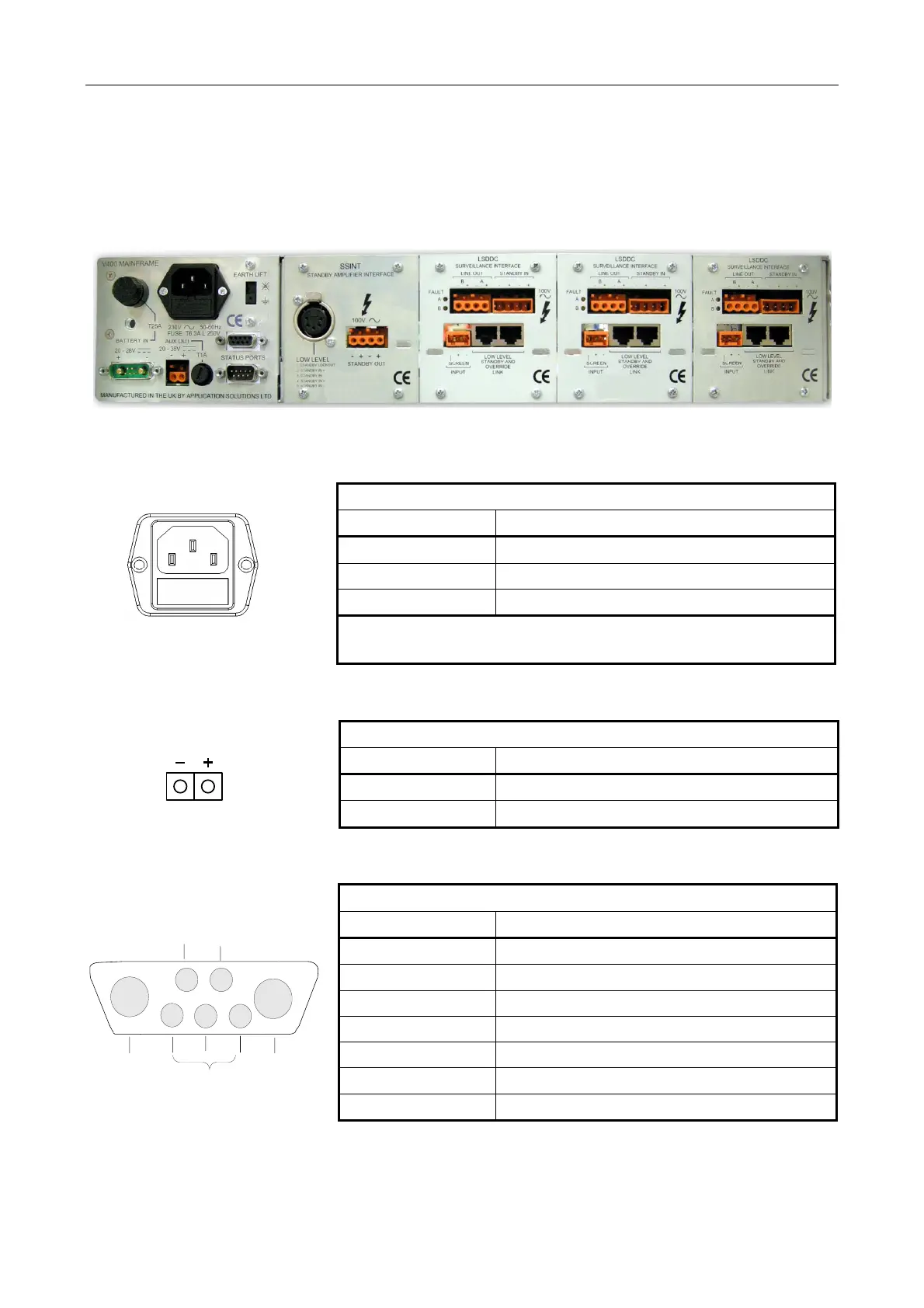
Figure 13 Rear of V400 with SSINT and LSDDC Interface Cards (Example)
SSINT LSDDC LSDDC LSDDC
AC MAINS INLET
L E N
MAINS SUPPLY: IEC 60320 STANDARD PLUG (MALE)
Signal Description
L Live
E Earth
N Neutral
Mains supply: European standard 230 V AC ±10% / 50-60Hz
Fuse: T6.3A L 250 V
AUXILIARY DC SUPPLY OUTPUT
AUXILIARY DC SUPPLY OUTPUT: 2 -WAY PLUGGABLE WAGO CAGE CLAMP (FEMALE)
Signal Description
“+” 100 V line audio output to loudspeaker circuit
“-“ 100 V line audio output to loudspeaker circuit
BATTERY CONNECTOR
4
1
5
3
2
A1
A2
FAULT RELAY
COMM
N/ON/C
GND REMOTE BATTERY
ON/OFF
BATTERY +
BATTERY -
BATTERY SUPPLY: MIXED CONTACT 7W – 2 (MALE)
Pin No Description
A1 Battery Positive
A2 Battery Negative
1 Ground Terminal
2 Remote battery ON/OFF
3 NC Fault Relay Contact
4 Common Fault Relay Contact
5 NO Fault Relay Contact