V400 – Installation Guide
U-0398-0607.doc – Issue: 03 complete, approved
Page 6 of 24
Equipment and Tool Requirements
• The V400 Amplifier Mainframe.
• M100, M200, or M400 amplifier modules as specified in your system design documentation.
• A mainframe front panel to suit the amplifier configuration.
• Cabling as specified in “External Cabling Requirements” (page 7) to suit your system design.
• A small flat-bladed screwdriver.
• Pozidriv screwdrivers (No 1 and No 3).
• A pair of wire cutters/strippers.
• A soldering iron.
• A 19-inch standard rack fitted with supporting rails and wired with AC power supply, signal, and control
wiring, as required by your specific system design.
!
!
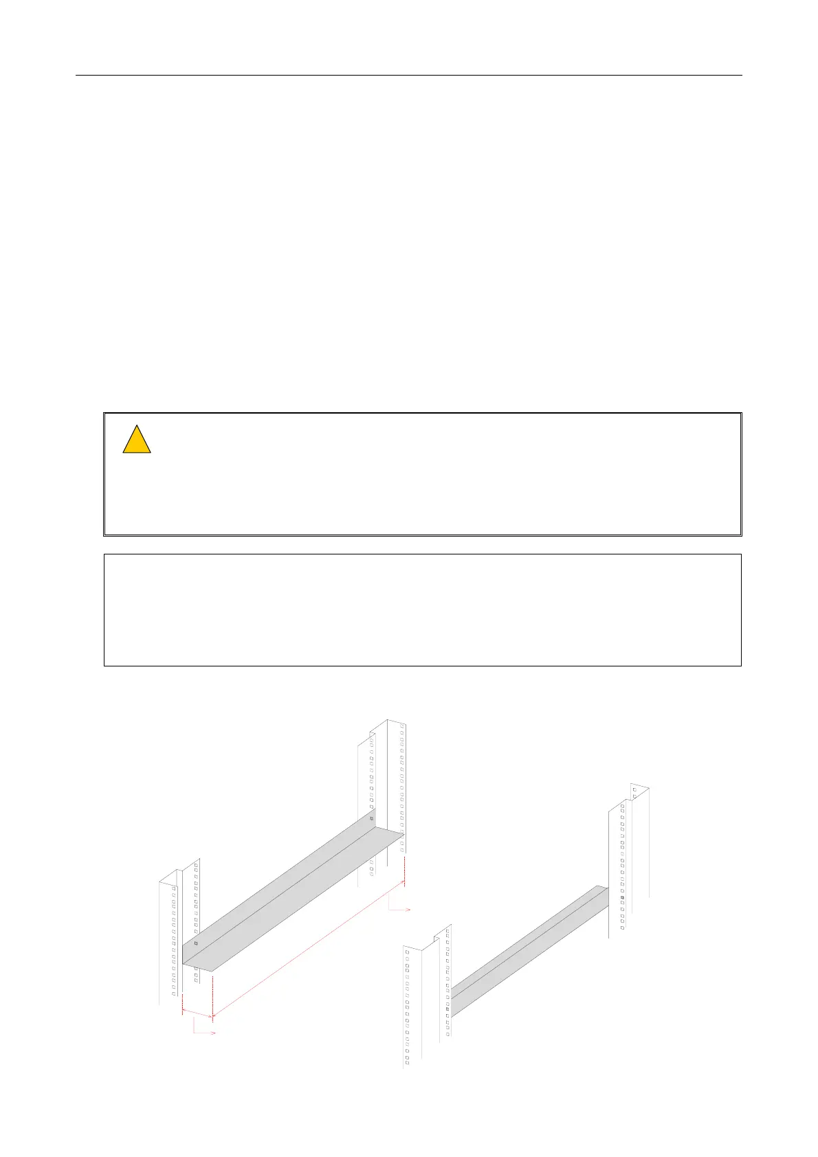
1) Ensure that the supporting rails extend at least 410 mm (mainframe depth) into the rack and
between 40 mm and 50 mm under the mainframe in order not to block the ventilation holes, yet
to prevent the mainframe from twisting and falling between the supports; see details in
Figure 1.
2) The supporting rails must be capable of safely bearing the weight of the equipment
(max. 20 kg).
1) ASL recommend a rear clearance depth of at least 110 mm for cabling.
A 19-inch standard rack with 600 mm depth provides the required room for installation including
the rear cabling.
2) In order for customers to produce their own site documentation drawings of the front and rear
panel are available from ASL.
Figure 1 19-inch Rack with Supporting Rails (Example)
FRONT OF RACK
LEFT-HAND SIDE
SUPPORTING
RAIL
RIGHT-HAND SIDE
SUPPORTING
RAIL
MINIMUM WIDTH = 40 mm
MAXIMUM WIDTH = 50 mm
MINIMUM DEPTH = 410 mm
(Rack and supporting rail design are example only.)
 Loading...