Option 1 (0-5v input / Mode 2 Operation Only) - The compressor speed input accepts a 0-5 VDC
analog voltage signal and will regulate the speed of the compressor automatically with respect to this
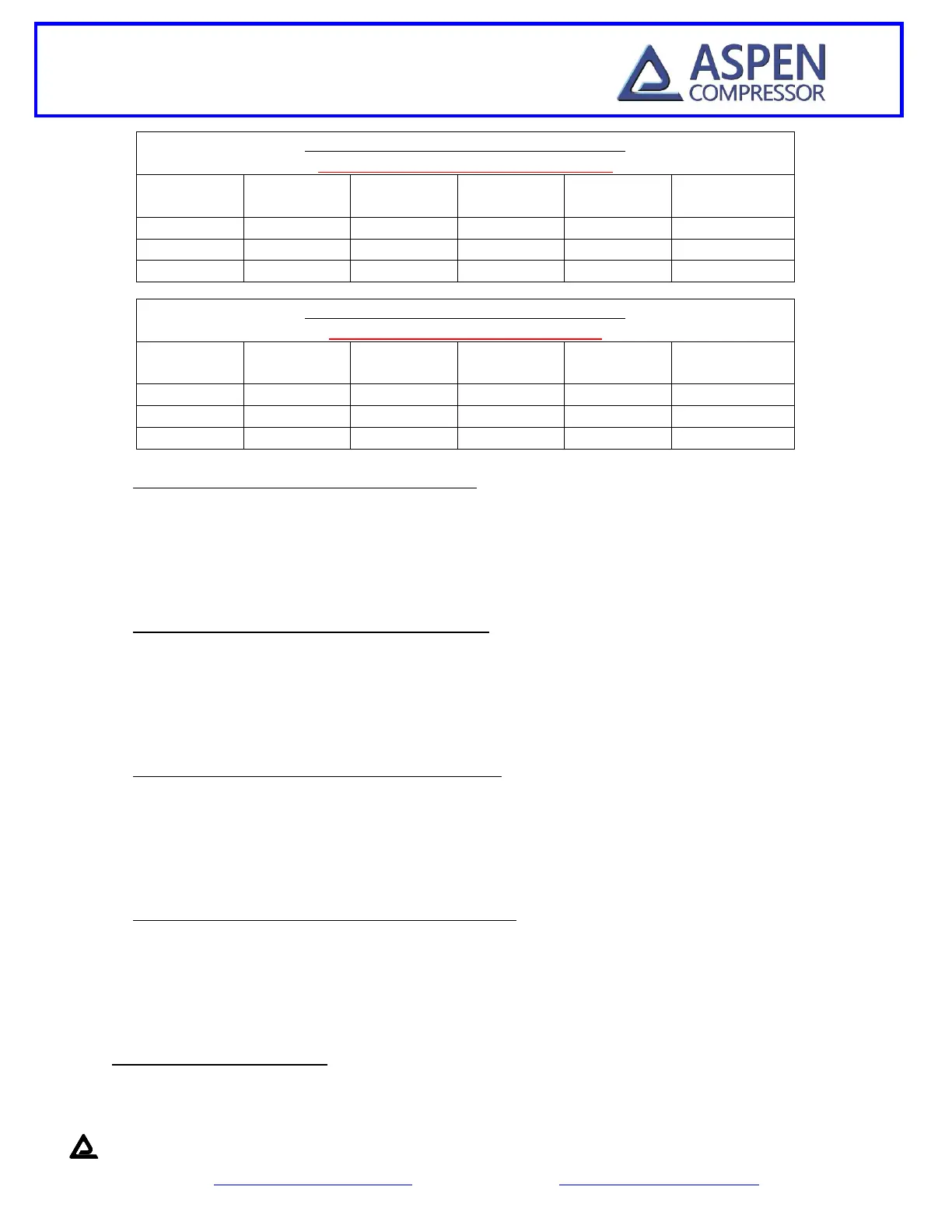
input voltage. There will be a linear increase in speed based on this input voltage. The charts above
show the different inputs and speed scaling relationships for both single and twin cylinder
compressors when using this option.
Option 2 (0-10 v input / Mode 2 Operation Only) - The compressor speed input accepts a 0-10 VDC
analog voltage signal and will regulate the speed of the compressor automatically with respect to this
input voltage. There will be a linear increase in speed based on this input voltage. The charts above
show the different inputs and speed scaling relationships for both single and twin cylinder
compressors when using this option.
Option 3 (4-20mA input / Mode 2 Operation Only) - The compressor speed input accepts a 4-20mA
input signal and will regulate the speed of the compressor automatically with respect to this input
signal. There will be a linear increase in speed based on this input signal. The charts above show the
different inputs and speed scaling relationships for both single and twin cylinder compressors when
using this option.
Option 4 (Frequency input / Mode 2 Operation Only) -.The compressor speed input accepts a
frequency input signal and will regulate the speed of the compressor automatically with respect to
this input signal. The frequency signal should be a 5 VDC, 50% duty cycle, square wave. There will be
a linear increase in speed based on this input signal. The charts above show the different inputs and
speed scaling relationships for both single and twin cylinder compressors when using this option.
9. Compressor Speed Low (TB15)
This tab should be used when a secondary power supply is being used to supply power for speed control
and the user wants the secondary supply to be isolated from the power supply being used to power the
 Loading...