Installation:
4
5
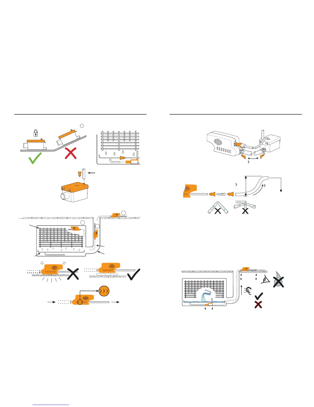
Fit breather tube to reservoir lid.
Install pump drive unit, above the ceiling where possible. Use sound dampening.
Secure horizontally. If using reservoir A , connect firmly to drainage pipe.
6
Note direction of water flow.
7
FROM RESERVOIR TO DRAIN
FALSE CEILING
EVAPORATOR COIL
CONDENSATE
DRAIN TRAY
CONDUIT
VINYL TUBE
EXAMPLE POSITIONS
1 ABOVE CEILING
2 INSIDE CONDUIT
3 BEHIND EVAPORATOR
15cm X 6mm o/d x 4mm
i/d vinyl tube
5 6
Installation:
8
11
9
Plug reservoir sensor cable into pump unit. Push the 6mm o/d x 9mm i/d tube
onto the reservoir and the pump. Secure with cable-ties. Ensure length is under
2 metres.
Wire the Mini Orange Pump to the permanent Live, Neutral and Earth terminals of
the Evaporator. Install a 1.0 amp in-line fuse between the Mini Orange Pump and
the Evaporator.
A high-level alarm switch should be wired into the cooling signal wire, to prevent the
continued operation of the Air-conditioning unit in the event of the pump
failing. These are volt-free contacts and operate as follows:
COMMON AND NORMALLY CLOSED when the water rises to the alarm level the
circuit opens.
COMMON AND NORMALLY OPEN when the water rises to the alarm level the
circuit closes.
12
TEST pump operation by pouring water into evaporator tray. Check for leaks.
Using the adaptor, connect the 6mm o/d pump outlet tube to the 9mm o/d
discharge tube. Channel discharge tube to an appropriate drain.
10
Avoid restrictions.
2m
8m
25m
APPROPRIATE
DRAIN
FALSE CEILING
1st run
In use