Do you have a question about the ASROCK 960GM-GS3 FX and is the answer not in the manual?
Legal notice regarding reproduction and use of the guide.
States specifications are for informational use and subject to change.
Information regarding Perchlorate in lithium batteries for California residents.
Lists all items included in the motherboard package.
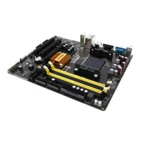
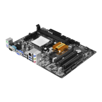
Details the rear I/O ports available on the motherboard.
Describes various internal connectors for system components like floppy, IDE, SATA.
Monitors system hardware like CPU temperature, fan speed, and voltage.
Lists supported OS and regulatory compliance details.
Provides safety warnings and important notes regarding setup and operation.
Lists important safety precautions before installing components.
Detailed steps for correctly installing the CPU into the socket.
Guide for installing the CPU cooler and applying thermal grease.
Describes the PCI and PCI Express slots for expansion cards.
Step-by-step guide for installing expansion cards into PCI/PCIe slots.
Configures +5VSB standby power for PS/2 or USB wake-up.
Resets CMOS data to default settings. Handle with care.
Connects to the floppy drive. Note red stripe on cable.
Connects to IDE devices. Uses 80-conductor ATA 66/100/133 cable.
Four SATAII connectors supporting SATA/SATAII HDDs for internal storage.
Connects SATA/SATAII drives or connectors to the motherboard.
Provides two USB 2.0 headers, each supporting two USB 2.0 ports.
Interface for connecting a printer cable.
Interface for front panel audio cable for convenient connection and control.
Connects the CPU fan. Supports 4-pin and 3-pin fans.
Accommodates various system front panel functions.
Connects the chassis speaker.
Connects chassis and power fan cables.
Connects the ATX power supply.
Connects the ATX 12V power supply for sufficient power.
Guide for installing system drivers from the support CD.
Instructions for installing Windows with RAID functions.
Instructions for installing Windows without RAID functions.
Steps for installing Windows 7/Vista without RAID functions.
Explains the Untied Overclocking Technology for improved stability.
Details about the motherboard's BIOS and how to access the setup utility.
Information on the drivers and utilities included on the support CD.
Configures +5VSB standby power for PS/2 or USB wake-up.
Resets CMOS data to default settings. Handle with care.
Connects to the floppy drive. Ensure red stripe on cable aligns with Pin 1.
Connects to IDE devices using an 80-conductor ATA 66/100/133 cable.
Four SATAII connectors supporting SATA/SATAII HDDs for internal storage.
Connects SATA/SATAII drives or connectors to the motherboard.
Provides two USB 2.0 headers, each supporting two USB 2.0 ports.
Interface for connecting a printer cable.
Interface for front panel audio cable for convenient connection and control.
Accommodates various system front panel functions.
Connects the chassis speaker.
Connects the CPU fan. Supports 4-pin and 3-pin fans.
Connects chassis and power fan cables.
Connects the ATX power supply. Supports 20-pin ATX power supply.
Connects the ATX 12V power supply for sufficient power.
Details about the motherboard's BIOS and how to access the setup utility.
Information on the drivers and utilities included on the support CD.
Lists all items included in the motherboard package.
Details the rear I/O ports available on the motherboard.
Describes various internal connectors for system components.
Details the BIOS features and support.
Lists drivers, utilities, and software included on the support CD.
Highlights unique motherboard features and utilities.
Provides warnings and important notes related to overclocking and memory installation.
Configures +5VSB standby power for PS/2 or USB wake-up.
Clears CMOS settings to factory defaults. Handle with care.
Connects to the floppy drive. Ensure red stripe on cable aligns with Pin 1.
Connects to IDE devices using an 80-conductor ATA 66/100/133 cable.
Four SATAII connectors supporting SATA/SATAII HDDs for internal storage.
Connects SATA/SATAII drives or connectors to the motherboard.
Provides two USB 2.0 headers, each supporting two USB 2.0 ports.
Interface for connecting a printer cable.
Interface for front panel audio cable for convenient connection and control.
Accommodates various system front panel functions.
Connects the chassis speaker.
Connects the CPU fan. Supports 4-pin and 3-pin fans.
Connects chassis and power fan cables.
Connects the ATX power supply. Supports 20-pin ATX power supply.
Connects the ATX 12V power supply for sufficient power.
Details about the motherboard's BIOS and how to access the setup utility.
Information on the drivers and utilities included on the support CD.
Lists all items included in the motherboard package.
Details the rear I/O ports available on the motherboard.
Describes various internal connectors for system components.
Details the BIOS features and support.
Lists drivers, utilities, and software included on the support CD.
Highlights unique motherboard features and utilities.
Explains jumper settings for system configuration and CMOS reset.
Configures +5VSB standby power for PS/2 or USB wake-up.
Clears CMOS settings to factory defaults. Handle with care.
Connects to the floppy drive. Ensure red stripe on cable aligns with Pin 1.
Connects to IDE devices using an 80-conductor ATA 66/100/133 cable.
Four SATAII connectors supporting SATA/SATAII HDDs for internal storage.
Connects SATA/SATAII drives or connectors to the motherboard.
Provides two USB 2.0 headers, each supporting two USB 2.0 ports.
Interface for connecting a printer cable.
Interface for front panel audio cable for convenient connection and control.
Accommodates various system front panel functions.
Connects the chassis speaker.
Connects the CPU fan. Supports 4-pin and 3-pin fans.
Connects chassis and power fan cables.
Connects the ATX power supply. Supports 20-pin ATX power supply.
Connects the ATX 12V power supply for sufficient power.
Details about the motherboard's BIOS and how to access the setup utility.
Information on the drivers and utilities included on the support CD.
Lists all items included in the motherboard package.
Details the rear I/O ports available on the motherboard.
Describes various internal connectors for system components.
Details the BIOS features and support.
Lists drivers, utilities, and software included on the support CD.
Highlights unique motherboard features and utilities.
Provides warnings and important notes related to overclocking and memory installation.
Configures +5VSB standby power for PS/2 or USB wake-up.
Clears CMOS settings to factory defaults. Handle with care.
Connects to the floppy drive. Ensure red stripe on cable aligns with Pin 1.
Connects to IDE devices using an 80-conductor ATA 66/100/133 cable.
Four SATAII connectors supporting SATA/SATAII HDDs for internal storage.
Connects SATA/SATAII drives or connectors to the motherboard.
Provides two USB 2.0 headers, each supporting two USB 2.0 ports.
Interface for front panel audio cable for convenient connection and control.
Interface for connecting a printer cable.
Accommodates various system front panel functions.
Connects the chassis speaker.
Connects the CPU fan. Supports 4-pin and 3-pin fans.
Connects chassis and power fan cables.
Connects the ATX power supply. Supports 20-pin ATX power supply.
Connects the ATX 12V power supply for sufficient power.
Details about the motherboard's BIOS and how to access the setup utility.
Information on the drivers and utilities included on the support CD.
Lists all items included in the motherboard package.
Details the rear I/O ports available on the motherboard.
Describes various internal connectors for system components.
Details the BIOS features and support.
Lists drivers, utilities, and software included on the support CD.
Monitors system hardware like CPU temperature, fan speed, and voltage.
Lists supported operating systems like Windows 7, Vista, and XP.
Details FCC, CE, and WHQL compliance.
Provides warnings and important notes related to overclocking and memory installation.
Provides important notes regarding motherboard setup and features.
Configures +5VSB standby power for PS/2 or USB wake-up.
Clears CMOS settings to factory defaults. Handle with care.
Connects to the floppy drive. Ensure red stripe on cable aligns with Pin 1.
Connects to IDE devices using an 80-conductor ATA 66/100/133 cable.
Four SATAII connectors supporting SATA/SATAII HDDs for internal storage.
Connects SATA/SATAII drives or connectors to the motherboard.
Provides two USB 2.0 headers, each supporting two USB 2.0 ports.
Interface for connecting a printer cable.
Interface for front panel audio cable for convenient connection and control.
Accommodates various system front panel functions.
Connects the chassis speaker.
Connects the CPU fan. Supports 4-pin and 3-pin fans.
Connects chassis and power fan cables.
Connects the ATX power supply. Supports 20-pin ATX power supply.
Connects the ATX 12V power supply for sufficient power.
Details about the motherboard's BIOS and how to access the setup utility.
Information on the drivers and utilities included on the support CD.
Lists all items included in the motherboard package.
Details the rear I/O ports available on the motherboard.
Describes various internal connectors for system components.
Details the BIOS features and support.
Lists drivers, utilities, and software included on the support CD.
Highlights unique motherboard features and utilities.
Provides warnings and important notes related to overclocking and memory installation.
Provides important notes regarding motherboard setup and features.
Configures +5VSB standby power for PS/2 or USB wake-up.
Clears CMOS settings to factory defaults. Handle with care.
Connects to the floppy drive. Ensure red stripe on cable aligns with Pin 1.
Connects to IDE devices using an 80-conductor ATA 66/100/133 cable.
Four SATAII connectors supporting SATA/SATAII HDDs for internal storage.
Connects SATA/SATAII drives or connectors to the motherboard.
Provides two USB 2.0 headers, each supporting two USB 2.0 ports.
Interface for connecting a printer cable.
Interface for front panel audio cable for convenient connection and control.
Accommodates various system front panel functions.
Connects the chassis speaker.
Connects the CPU fan. Supports 4-pin and 3-pin fans.
Connects chassis and power fan cables.
Connects the ATX power supply. Supports 20-pin ATX power supply.
Connects the ATX 12V power supply for sufficient power.
Details about the motherboard's BIOS and how to access the setup utility.
Information on the drivers and utilities included on the support CD.
| Memory channels | Dual-channel |
|---|---|
| Memory slots type | DIMM |
| Number of memory slots | 2 |
| Supported memory types | DDR3-SDRAM |
| Maximum internal memory | 8 GB |
| Supported memory clock speeds | 800, 1066, 1333, 1600, 1800 MHz |
| System bus rate | 5.2 GT/s |
| Processor socket | Socket AM3+ |
| Processor manufacturer | AMD |
| Compatible processor series | AMD Phenom II X2, AMD Phenom II X3, AMD Phenom II X4, AMD Phenom II X6 |
| Processor system buses supported | 2600 MHz |
| Power fan connector | Yes |
| Number of SATA II connectors | 4 |
| Number of SATA III connectors | - |
| Number of Parallel ATA connectors | 1 |
| USB 2.0 ports quantity | USB 2.0 ports have a data transmission speed of 480 Mbps, and are backwards compatible with USB 1.1 ports. You can connect all kinds of peripheral devices to them. |
| Firewire (IEEE 1394) ports | 0 |
| Audio chip | Realtek ALC662 |
| Certification | FCC, CE, WHQL, ErP/EuP |
| Component for | PC |
| Power source type | ATX |
| Motherboard chipset | AMD 760G |
| Audio output channels | 5.1 channels |
| Motherboard form factor | micro ATX |
| Motherboard southbridge | AMD SB710 |
| Compatible operating systems | Microsoft Windows 7 / 7 64-bit / Vista / Vista 64-bit / XP / XP Media Center / XP 64-bit compliant |
| Supported storage drive interfaces | SATA |
| Graphics card | Radeon 3000 |
| Maximum graphics card memory | 512 MB |
| Parallel processing technology support | Not supported |
| Bluetooth | No |
| LAN controller | Realtek RTL8111E |
| Ethernet interface type | Gigabit Ethernet |
| Depth | 183 mm |
|---|---|
| Width | 244 mm |