12
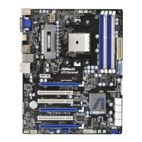
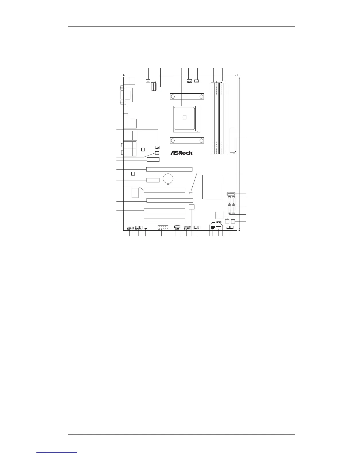
1.3 Motherboard Layout
1 Power Fan Connector (PWR_FAN1) 22 Chassis Fan Connector (CHA_FAN1)
2 ATX 12V Power Connector (ATX12V1) 23 Infrared Module Header (IR1)
3 CPU Heatsink Retention Module 24 Power LED Header (PLED1)
4 CPU Socket 25 USB 2.0 Header (USB10_11, Black)
5 CPU Fan Connector (CPU_FAN1) 26 SPI Flash Memory (32Mb)
6 CPU Fan Connector (CPU_FAN2) 27 USB 2.0 Header (USB8_9, Black)
7 2 x 240-pin DDR3 DIMM Slots 28 USB 2.0 Header (USB6_7, Black)
(Dual Channel A: DDR3_A1, DDR3_B1; Black) 29 Consumer Infrared Module Header (CIR1)
8 2 x 240-pin DDR3 DIMM Slots 30 COM Port Header (COM1)
(Dual Channel B: DDR3_A2, DDR3_B2; Black) 31 HDMI_SPDIF Header (HDMI_SPDIF1, Black)
9 ATX Power Connector (ATXPWR1) 32 Front Panel IEEE 1394 Header
10 Clear CMOS Jumper (CLRCMOS1) (FRONT_1394, Black)
11 Southbridge Controller 33 Front Panel Audio Header (HD_AUDIO1, Black)
12 SATA3 Connector (SATA3_5, Gray) 34 PCI Slot (PCI3)
13 SATA3 Connector (SATA3_4, Gray) 35 PCI Slot (PCI2)
14 SATA3 Connector (SATA3_3, Gray) 36 PCI Express 2.0 x16 Slot (PCIE4; Black)
15 SATA3 Connector (SATA3_1, Gray) 37 PCI Slot (PCI1)
16 SATA3 Connector (SATA3_2, Gray) 38 PCI Express 2.0 x1 Slot (PCIE3; Black)
17 Dr. Debug (LED) 39 PCI Express 2.0 x16 Slot (PCIE2; Black)
18 Power Switch (PWRBTN) 40 PCI Express 2.0 x1 Slot (PCIE1; Black)
19 Reset Switch (RSTBTN) 41 Chassis Fan Connector (CHA_FAN2)
20 System Panel Header (PANEL1, Black) 42 Chassis Fan Connector (CHA_FAN3)
21 Chassis Speaker Header (SPEAKER 1, Black)
Super
I/O
CM OS
BA TTE RY
ATXPWR1
AMD
A75 FCH
(Hudson-D3)
Chipset
COM1
PCIE 1
PCI1
LAN
AUDI O
CODE C
1
CLRC MOS1
1
CPU_ FAN1
HDLED R ESET
PLED PW RBTN
1
PANEL 1
CHA_ FAN1
SPEA KER1
1
HD_ AUDI O1
1
30.5 cm (12.0-in)
22.4cm (8.8-in)
6
7
1
2
4
3
5
8
9
10
11
12
13
14
15
16
17
18
19
20
21
22
23
24
25
2627
28
29
32Mb
BIOS
IR1
1
PCIE 2
HDMI1
Top:
CTR BA SS
Cen ter :
REA R S PK
Bot tom :
Opt ica l
SPD IF
Top:
LIN E I N
Cen ter :
FRO NT
Bot tom :
MIC IN
1
USB6 _7
CPU _FAN2
A75 Pro4/MVP
ErP/EuP Ready
R oHS
DDR3 2400+
USB 3.0
T: USB 4
B: U SB5
CIR1
1
SATA3 6Gb/s
ATX1 2V1
HDMI 1.4a
Ps2
Key bo ard /
Mou se
SOCKET FM1
PCIE 4
Dr.
Debug
PWRB TN
RSTB TN
PLED 1
1
SATA3_ 1
SATA3_ 2
SATA3_ 3
SATA3_ 4
DDR3_A1 (6 4 b it, 240 - pin module)
DDR3_A2 (6 4 b it, 240 - pin module)
DDR3_B1 (6 4 b it, 240-pin mo dule)
DDR3_B2 (6 4 b it, 240 - pin module)
PWR _FAN1
FRON T_13 94
1
1
HDMI _SPDI F1
1
USB8 _9
1
USB1 0_11
VGA1
DVI_ CO N1
Clr
CM O S
USB 2. 0
T: USB2
B: US B3
IEE E 1 394
eSATA1
Top:
RJ-45
USB 3. 0
T: U SB 0
B: USB1
CHA _FAN3
CHA _FAN2
USB 3.0
1394a
303132
33
34
35
36
37
38
39
40
41
42
PCIE 3
PCI2
PCI3
SATA3_ 5
DX11
X
Fast USB
Desi gn ed i n Taip ei
Dual Graphics