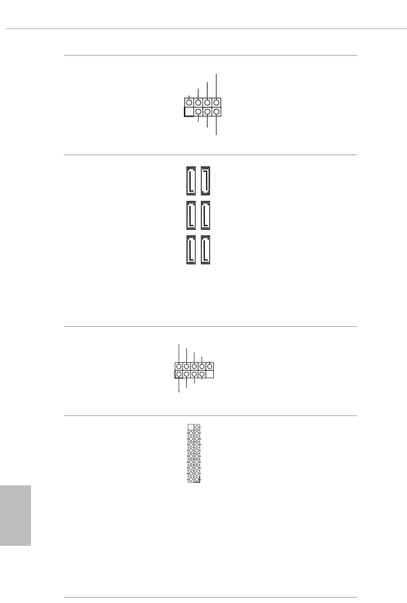
28
Power LED and Speaker
Header
(7-pin SPK_PLED1)
(see p.1, No. 17)
Please connect the
chassis power LED and
the chassis speaker to this
header.
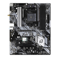
Serial ATA3 Connectors
(SATA3_1:
see p.1, No. 11)
(SATA3_2:
see p.1, No. 10)
(SATA3_3:
see p.1, No. 13)
(SATA3_4:
see p.1, No. 12)
(SATA3_5:
see p.1, No. 14)
(SATA3_6:
see p.1, No. 15)
ese six SATA3
connectors support SATA
data cables for internal
storage devices with up to
6.0 Gb/s data transfer rate.
* M2_2 and SATA3_5_6 share
lanes. If either one of them is
in use, the other one will be
disabled.
USB 2.0 Headers
(9-pin USB_3_4)
(see p.1, No. 22)
(9-pin USB_5_6)
(see p.1, No. 23)
ere are two headers
on this motherboard.
Each USB 2.0 header can
support two ports.
USB 3.2 Gen1 Headers
(19-pin F_USB3_1_2)
(see p.1, No. 9)
ere are two headers on
this motherboard. Each
USB 3.2 Gen1 header can
support two ports.
1
+5V
DUMMY
PLED+
PLED+
PLED-
DUMMY
SPEAKER
DUMMY
GND
GND
P+
P-
USB_PWR
P+
P-
USB_PWR
1
IntA_PB_D+
Dummy
IntA_PB_D-
GND
IntA_PB_SSTX+
GND
IntA_PB_SSTX-
IntA_PB_SSRX+
IntA_PB_SSRX-
VbusVbus
Vbus
IntA_PA_SSRX-
IntA_PA_SSRX+
GND
IntA_PA_SSTX-
IntA_PA_SSTX+
GND
IntA_PA_D-
IntA_PA_D+
SATA3_4
SATA3_3
SATA3_6
SATA3_5
SATA3_1
SATA3_2