B550D4-4L
26 27
English
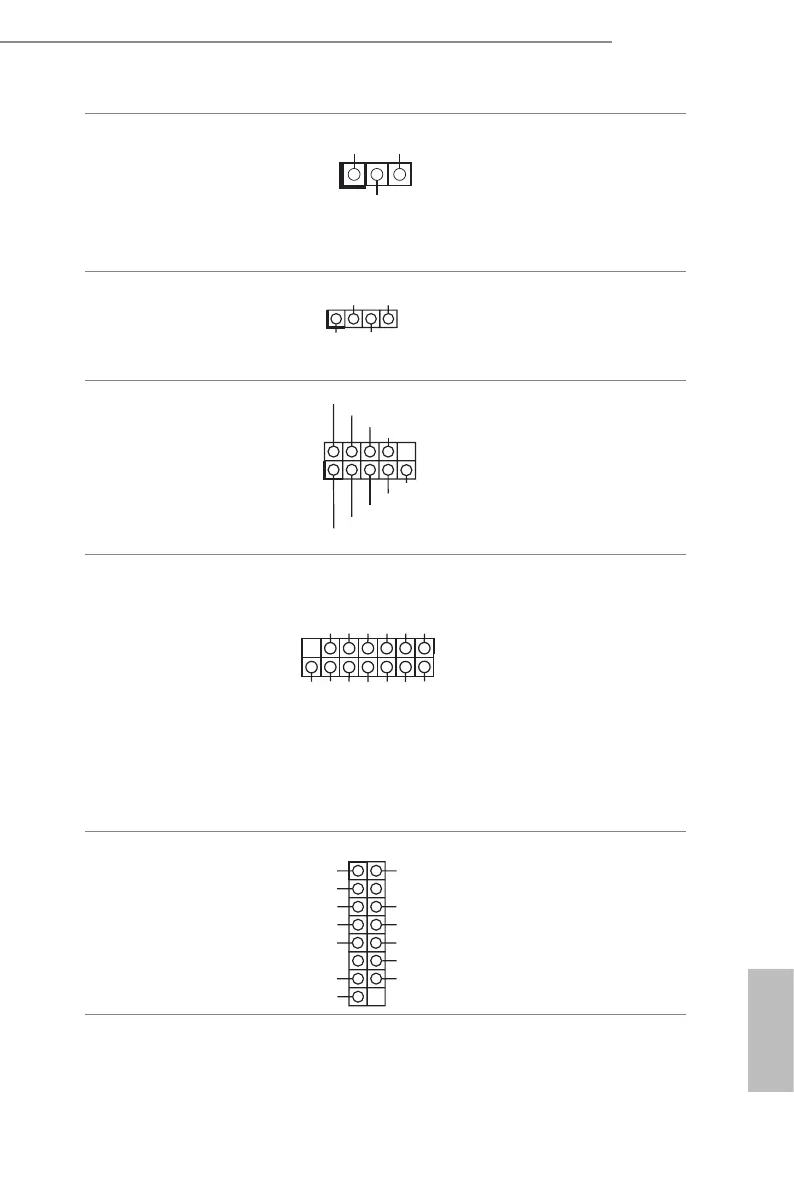
ermal Sensor Header
(3-pin TR1)
(see p.6, No. 33)
1
TR1 TR1
GND
Please connect the thermal
sensor cable to either pin 1-2
or pin 2-3 and the other end to
the device which you wish to
monitor its temperature.
Chassis Speaker Header
(4-pin SPEAKER1)
(see p.6, No. 30)
1
+5V
DUMMY
DUMMY
SPEAKER
Please connect the chassis
speaker to this header.
Serial Port Header
(9-pin COM2)
(see p.6, No. 31)
CCTS#1
RRTS#1
DDSR#1
DDTR#1
RRXD1
GND
TTXD1
DDCD#1
1
RRI#1
is COM header supports a
serial port module.
TPM-SPI Header
(13-pin TPM_BIOS_PH1)
(see p.6, No. 34)
SPI_WP
SPI_CS
MISO
RSMRST#
TPM_CS#
SPI PIRQ
SPI_RST
MOSI
SPI_CLK
+3.3V
GND
SPI_HOLD
X
1
is connector supports
Trusted Platform Module
(TPM) system for SPI
interface, which can securely
store keys, digital certicates,
passwords, and data. A TPM
system also helps enhance
network security, protects
digital identities, and ensures
platform integrity.
Front VGA Header
(15-pin FRNT_VGA1)
(see p.6, No. 1)
GND
Green
DDC_DATA
V_SYNC
Red
DDC_CLK
+5V
H_SYNC
GND
GND
Blue
GND
GND
Please connect either end
of VGA_2X8 cable to VGA
header.
 Loading...