18
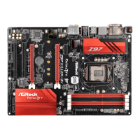
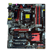
Fatal1ty P67 Performance Series Motherboard
English
2.4 Expansion Slots (PCI and PCI Express Slots)
There are 3 PCI slots and 4 PCI Express slots on this motherboard.
PCI slots: PCI slots are used to install expansion cards that have the 32-bit PCI
interface.
PCIE slots:
PCIE1 / PCIE3 / PCIE4 (PCIE x1 slot; Black) is used for PCI Express
cards with x1 lane width cards, such as Gigabit LAN card, SATA2 card,
etc.
PCIE2 (PCIE x16 slot; Red) is used for PCI Express x16 lane width
graphics cards.
Installing an expansion card
Step 1. Before installing the expansion card, please make sure that the power
supply is switched off or the power cord is unplugged. Please read the
documentation of the expansion card and make necessary hardware
settings for the card before you start the installation.
Step 2. Remove the system unit cover (if your motherboard is already installed
in a chassis).
Step 3. Remove the bracket facing the slot that you intend to use. Keep the
screws for later use.
Step 4. Align the card connector with the slot and press fi rmly until the card is
completely seated on the slot.
Step 5. Fasten the card to the chassis with screws.
Step 6. Replace the system cover.
 Loading...