4
Fatal1ty P67 Performance Series Motherboard
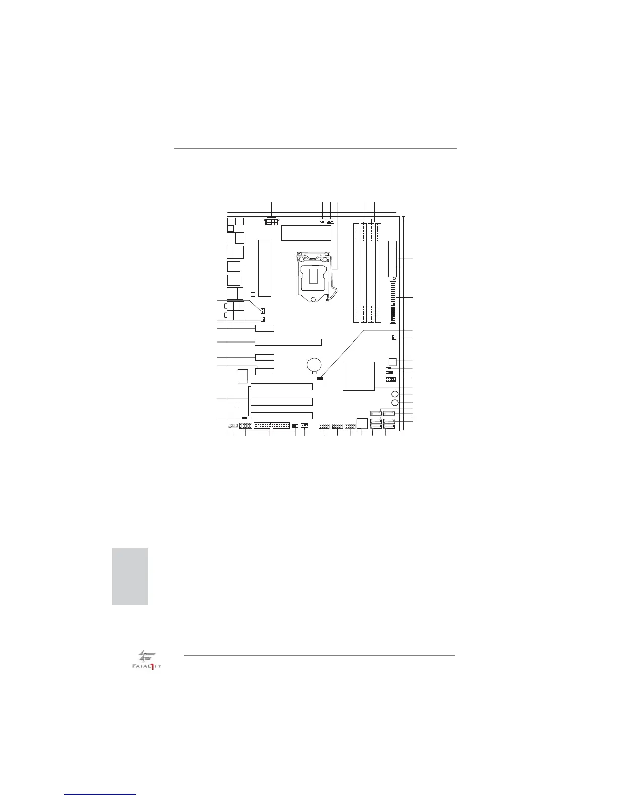
Motherboard Layout
English
1 ATX 12V Power Connector (ATX12V1) 21 SATA2 Connector (SATA2_2, Black)
2 CPU Fan Connector (CPU_FAN2) 22 SATA2 Connector (SATA2_4, Black)
3 CPU Fan Connector (CPU_FAN1) 23 SATA2 Connector (SATA2_5, Black)
4 1155-Pin CPU Socket 24 Dr. Debug
5 2 x 240-pin DDR3 DIMM Slots 25 USB 2.0 Header (USB12_13, Black)
(Dual Channel: DDR3_A1, DDR3_B1, Red) 26 USB 2.0 Header (USB10_11, Black)
6 2 x 240-pin DDR3 DIMM Slots 27 USB 2.0 Header (USB8_9, Black)
(Dual Channel: DDR3_A2, DDR3_B2, Black) 28 Chassis Fan Connector (CHA_FAN1)
7 ATX Power Connector (ATXPWR1) 29 Infrared Module Header (IR1)
8 Primary IDE Connector (IDE1, Black) 30 Floppy Connector (FLOPPY1)
9 Clear CMOS Jumper (CLRCMOS1) 31 COM Port Header (COM1)
10 Chassis Fan Connector (CHA_FAN2) 32 Front Panel Audio Header
11 64Mb SPI Flash (HD_AUDIO1, Black)
12 Power LED Header (PLED1) 33 HDMI_SPDIF Header
13 Chassis Speaker Header (SPEAKER 1, Black) (HDMI_SPDIF1, Black)
14 System Panel Header (PANEL1, Black) 34 PCI Slots (PCI1-3)
15 Intel P67 Chipset 35 PCI Express 2.0 x1 Slot (PCIE4, Black)
16 Power Switch (PWRBTN) 36 PCI Express 2.0 x1 Slot (PCIE3, Black)
17 Reset Switch (RSTBTN) 37 PCI Express 2.0 x16 Slot (PCIE2, Red)
18 SATA3 Connector (SATA3_1, Red) 38 PCI Express 2.0 x1 Slot (PCIE1, Black)
19 SATA3 Connector (SATA3_0, Red) 39 Chassis Fan Connector (CHA_FAN3)
20 SATA2 Connector (SATA2_3, Black) 40 Power Fan Connector (PWR_FAN1)
Intel
P67
24.4cm (9.6 in)
30.5cm (12.0 in)
DDR3_A1 (64 bit, 240-pin module)
DDR3_A2 (64 bit, 240-pin module)
DDR3_B1 (64 bit, 240-pin module)
DDR3_B2 (64 bit, 240-pin module)
ATXPWR1
CHA_FAN1
CLRCMOS1
1
ATX12V1
CHA_FAN2
CPU_FAN1
CPU_FAN2
Fatal1ty
P67 Performance
64Mb
BIOS
PWRBTN
Dr.
Debug
Super
I/O
PCIE1
PCIE2
PCI1
CMOS
Battery
SATA2_5 SATA2_4
HDLED RESET
PLED PWRBTN
PANEL1
1
SPEAKER1
1
PLED1
1
USB12_13
1
USB10_11
1
1
HD_AUDIO1
FLOPPY1
COM1
1
IR1
1
1
HDMI_SPDIF1
LAN
PHY
AUDIO
CODEC
PS2
Mouse
Coaxial
SPDIF
PS2
Keyboard
Optical
SPDIF
Clr
CMOS
USB 2.0
T: U SB 4
B: USB5
Top:
RJ-45
USB 2.0
T:USB0
B: USB1
Top:
SIDE SPK
Center:
REAR SPK
Top:
LINE IN
Center:
FRONT
Bottom:
CTR BASS
Bottom:
MIC IN
USB 2.0
T: U SB 6
B: USB7
eSATA
PWR_FAN1
Dual Channel
PCI Express 2.0
ErP/EuP Ready
RoHS
USB 3.0
Designed in Taipei
SATA3 6Gb/s
1
2
3
4
5
6
7
11
12
13
14
16
8
9
10
15
17
18
24
19
20
21
22
23
2526272829
30
31
32
33
34
35
36
37
38
39
PCIE3
PCIE4
PCI2
PCI3
SATA2_3 SATA2_2
SATA3_1 SATA3_0
CHA_FAN3
DDR3 2133
USB 3.0
T: U SB 2
B: USB3
IDE1
RSTBTN
USB8_9
1
40
 Loading...