HDLED (Hard Drive Activity LED):
Connect to the hard drive activity LED on the chassis front panel. The
LED is on when the hard drive is reading or writing data.
The front panel design may differ by chassis. A front panel module
mainly consists of power switch, reset switch, power LED, hard drive
activity LED, speaker and etc. When connecting your chassis front
panel module to this header, make sure the wire assignments and the
pin assign-ments are matched correctly.
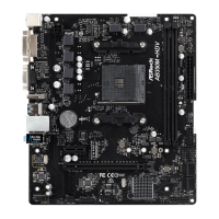
Chassis and Power Fan Please connect the fan cable
Connectors to the fan connector and
(4-pin CHA_FAN1)
match the black wire to the
(see p.1 No. 15)
ground pin.
(3-pin PWR_FAN1)
(see p.1 No. 21)
+12V
CHA_FAN_SPEED
FAN_SPEED_CONTROL
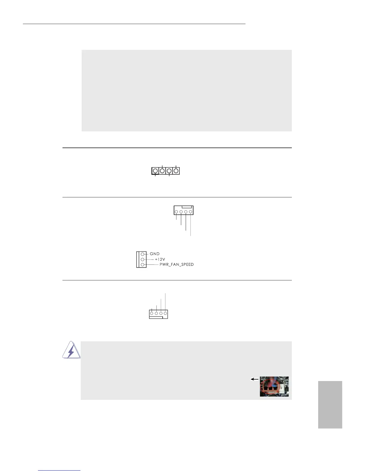
Though this motherboard provides 4-Pin CPU fan (Quiet Fan) support, the 3-Pin
CPU fan still can work successfully even without the fan speed control function.
If you plan to connect the 3-Pin CPU fan to the CPU fan connector on this
motherboard, please connect it to Pin 1-3.
Pin 1-3 Connected
3-Pin Fan Installation
CPU Fan Connector Please connect the CPU fan
(4-pin CPU_FAN1)
cable to the connector and
(see p.1 No. 2)
match the black wire to the
ground pin.
GND
+12V
 Loading...