1111
1111
11
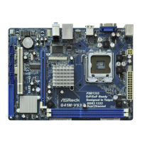
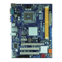
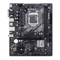
ASRock G41C-GS R2.0 Motherboard
EnglishEnglish
EnglishEnglish
English
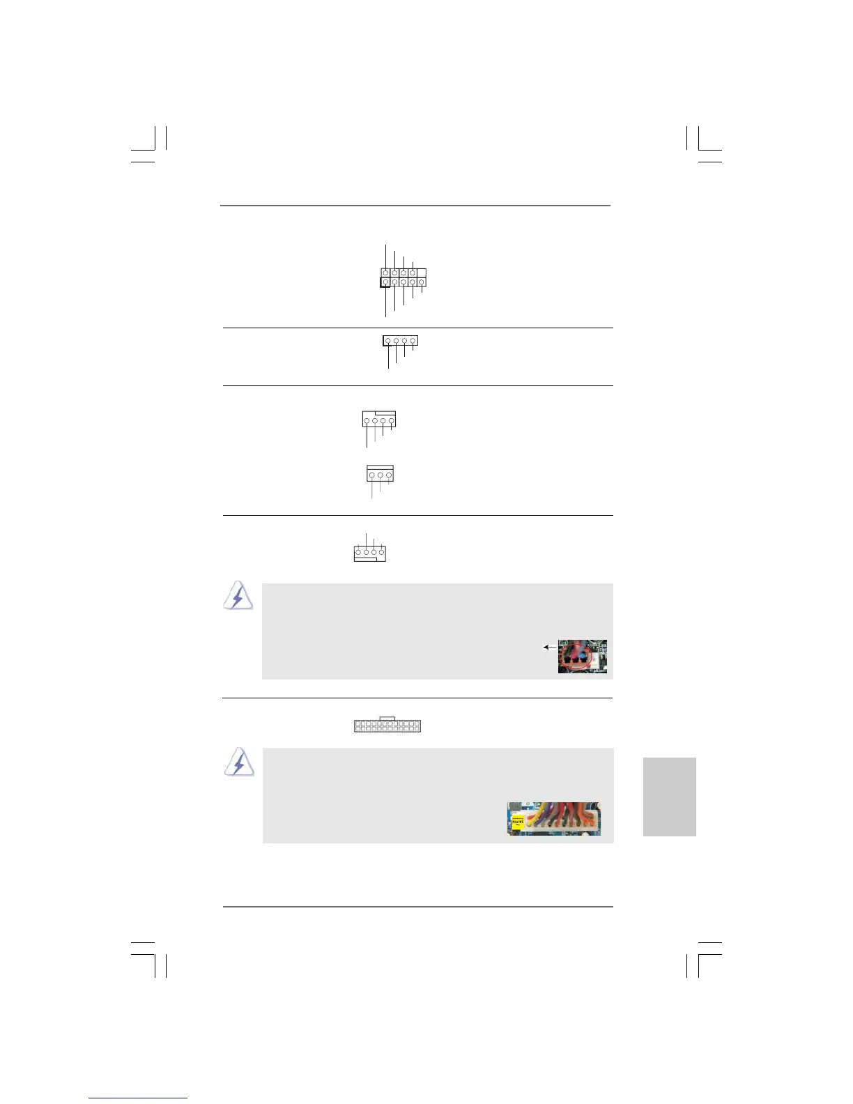
20-Pin ATX Power Supply Installation
ATX Power Connector Please connect an ATX power
(24-pin ATXPWR1) supply to this connector.
(see p.2 No. 4)
Though this motherboard provides 24-pin ATX power connector, it can still work
if you adopt a traditional 20-pin ATX power supply. To use the 20-pin ATX power
supply, please plug your power supply along with Pin 1 and Pin 13.
24 13
12 1
24 13
12 1
+5V
DUMMY
DUMMY
SPEAKER
1
GND
PWRBTN#
PLED-
PLED+
DUMMY
RESET#
GND
HD LED+
HD LED -
1
System Panel Header This header accommodates
(9-pin PANEL1) several system front panel
(see p.2 No. 17) functions.
Chassis Speaker Header Please connect the chassis
(4-pin SPEAKER 1) speaker to this header.
(see p.2 No. 12)
Chassis and Power Fan Connectors Please connect the fan cables
(4-pin CHA_FAN1) to the fan connectors and
(see p.2 No. 8) match the black wire to the
ground pin.
(3-pin PWR_FAN1)
(see p.2 No. 7)
CPU Fan Connector Please connect a CPU fan cable
(4-pin CPU_FAN1) to this connector and match
(see p.2 No. 3) the black wire to the ground pin.
GND
+12V
CPU_FAN_SPEED
FAN_S PEED_CONTROL
1 2 3 4
Though this motherboard provides 4-Pin CPU fan (Quiet Fan) support, the 3-Pin
CPU fan still can work successfully even without the fan speed control function.
If you plan to connect the 3-Pin CPU fan to the CPU fan connector on this
motherboard, please connect it to Pin 1-3.
3-Pin Fan Installation
Pin 1-3 Connected
GND
+12V
FAN_SPEED
FAN_SPEED
FAN_SPEED_CONTROL
+12V
GND
 Loading...