1212
1212
12
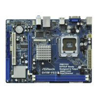
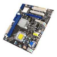
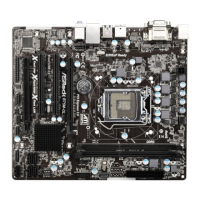
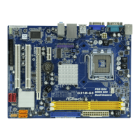
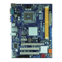
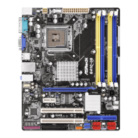
ASRock G41C-GS R2.0 Motherboard
2. BIOS Information2. BIOS Information
2. BIOS Information2. BIOS Information
2. BIOS Information
The Flash Memory on the motherboard stores BIOS Setup Utility. When you start up
the computer, please press <F2> during the Power-On-Self-Test (POST) to enter
BIOS Setup utility; otherwise, POST continues with its test routines. If you wish to
enter BIOS Setup after POST, please restart the system by pressing <Ctl> + <Alt> +
<Delete>, or pressing the reset button on the system chassis. The BIOS Setup pro-
gram is designed to be user-friendly. It is a menu-driven program, which allows you to
scroll through its various sub-menus and to select among the predetermined choices.
For the detailed information about BIOS Setup, please refer to the User Manual (PDF
file) contained in the Support CD.
3. Software Support CD information3. Software Support CD information
3. Software Support CD information3. Software Support CD information
3. Software Support CD information
This motherboard supports various Microsoft
®
Windows
®
operating systems: 7 / 7
64-bit / Vista
TM
/ Vista
TM
64-bit / XP / XP 64-bit. The Support CD that came with the
motherboard contains necessary drivers and useful utilities that will enhance
motherboard features. To begin using the Support CD, insert the CD into your CD-
ROM drive. It will display the Main Menu automatically if “AUTORUN” is enabled in
your computer. If the Main Menu does not appear automatically, locate and double-
click on the file “ASRSETUP.EXE” from the BIN folder in the Support CD to display the
menus.
EnglishEnglish
EnglishEnglish
English
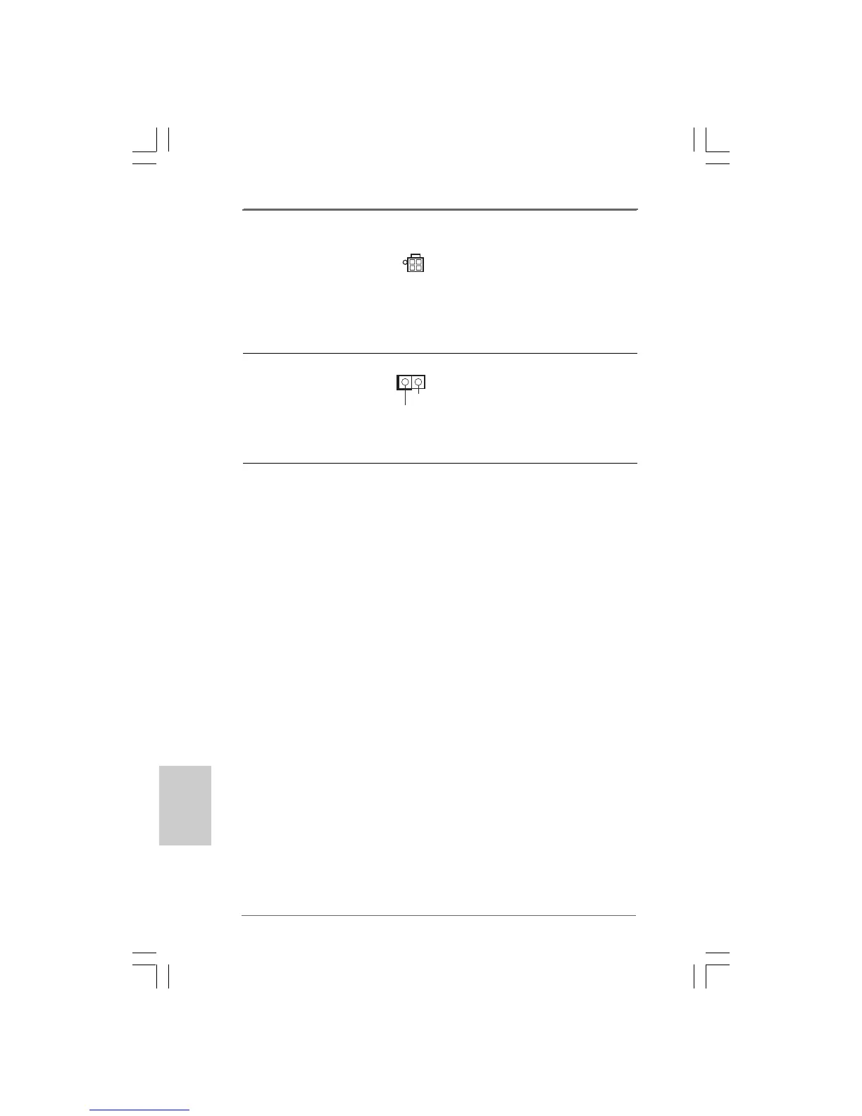
ATX 12V Connector Please note that it is necessary
(4-pin ATX12V2) to connect a power supply with
(see p.2 No. 2) ATX 12V plug to this connector
so that it can provides sufficient
power. Failing to do so will cause
the failure to power up.
Chassis Intrusion Header This motherboard supports CASE
(2-pin CI1) OPEN detection feature that
(see p.2 No. 21) detects if the chassis cover has
been removed. This feature
requires a chassis with chassis
intrusion detection design.
1
Signal
GND
 Loading...