88
88
8
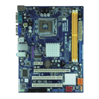
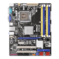
ASRock G41C-GS R2.0 Motherboard
EnglishEnglish
EnglishEnglish
English
1.3 Jumpers Setup1.3 Jumpers Setup
1.3 Jumpers Setup1.3 Jumpers Setup
1.3 Jumpers Setup
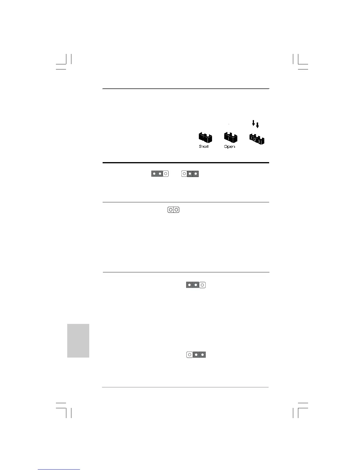
The illustration shows how jumpers are setup.
When the jumper cap is placed on
pins, the jumper is “Short”. If no jumper cap is
placed on pins, the jumper is “Open”. The il-
lustration shows a 3-pin jumper whose pin1
and pin2 are “Short” when jumper cap is placed
on these 2 pins.
Jumper Setting Description
PS2_USB_PWR1 Short pin2, pin3 to enable
(see p.2 No. 1) +5VSB (standby) for PS/2
or USB wake up events.
Note: To select +5VSB, it requires 2 Amp and higher standby current provided by power
supply.
Clear CMOS
(CLRCMOS1, 2-pin jumper)
(see p.2 No. 20)
Note: CLRCMOS1 allows you to clear the data in CMOS. The data in CMOS includes
system setup information such as system password, date, time, and system
setup parameters. To clear and reset the system parameters to default setup,
please turn off the computer and unplug the power cord from the power supply.
After waiting for 15 seconds, use a jumper cap to short 2 pins on CLRCMOS1 for
5 seconds.
+5V
1_2
+5VSB
2_3
2-pin jumper
EUP Audio Jumper
(EUP_AUDIO1, 3-pin jumper)
(see p.2 No. 23)
Note: EUP_AUDIO jumper design decreases the power consumption of this motherboard
to meet EuP standard. With an ASRock EuP ready motherboard and a power
supply that the 5VSB power efficiency is higher than 50% under 100mA current
consumption, your system is able to submit EuP standard. The default setting
(short pin1 and pin2) is EuP enabled. If you want to disable this power saving
function, you may short pin2 and pin3.
EUP_LAN1
EUP_AUDIO1
(Disable EuP)
EUP_LAN1
EUP_AUDIO1
Default (Enable EuP)
 Loading...