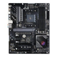
Do you have a question about the ASROCK H670 PG Riptide and is the answer not in the manual?
Lists all items included in the motherboard package.
Details the technical specifications of the motherboard hardware components.
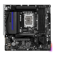
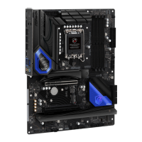
Diagram and labels of motherboard components and connectors.
Description and layout of the rear panel input/output ports.
Important safety and handling guidelines before installing components.
Step-by-step guide for safely installing the CPU onto the motherboard socket.
Instructions on mounting the CPU cooler and fan assembly.
Guide on how to install DDR4 memory modules into the DIMM slots.
Information on the types and configurations of PCIe expansion slots.
Explanation of jumper settings, specifically the Clear CMOS jumper.
Details and diagrams for various onboard headers and connectors.
Instructions for using the BIOS Flashback button for updating the BIOS.
Explanation of the Post Status Checker feature for diagnosing boot issues.
Guide on setting up AMD CrossFire technology with multiple graphics cards.
Instructions for installing M.2 WiFi/BT modules and Intel CNVi.
Guide for installing M.2 NVMe SSDs into the M2_1 slot.
Guide for installing M.2 NVMe SSDs into the M2_2 slot.
Guide for installing M.2 NVMe SSDs into the M2_3 slot.
Steps to install necessary drivers from the support CD or online.
Guide to using the ASRock utility for system tuning and monitoring.
Information on ASRock's utility for updating software and downloading applications.
Details on the Nahimic audio software for enhanced sound performance.
Guide for customizing RGB lighting effects using ASRock Polychrome SYNC.
Overview of the UEFI Setup Utility and how to access it.
Explanation of the BIOS EZ Mode interface for system status overview.
Introduction to the Advanced Mode for detailed BIOS configuration options.
Description of the UEFI BIOS Main screen and system overview.
Guide to the OC Tweaker screen for overclocking system settings.
Overview of advanced configuration options within the UEFI utility.
Settings related to CPU performance, threading, and power management.
Configuration options for the motherboard chipset and its features.
Settings for SATA controllers, storage modes, and SMART technology.
Configuration options for Thunderbolt support and connectivity.
Settings for Super I/O devices like PS2 Y-Cable.
Advanced Configuration and Power Interface settings for power management.
Settings related to USB controllers, legacy support, and hand-off.
Options for enabling BIOS support for security devices like TPM.
Access to utility tools like ASRock Polychrome RGB and RAID installer.
Monitoring system hardware status, temperatures, voltages, and fan speeds.
Options for setting supervisor/user passwords and secure boot.
Configuration of boot settings, boot priority, and CSM options.
Options for saving or discarding changes and exiting the UEFI setup.
Contact details for ASRock's headquarters in Taiwan.
Contact details for ASRock's European branch in the Netherlands.
Contact details for ASRock's North American branch in the USA.
Identifies the responsible party for product compliance.
Specifies the name of the product being declared compliant.
Provides additional details on FCC compliance and operating conditions.
Identifies the equipment covered by the EU declaration.
Manufacturer's name and address for EU conformity.
EU representative's contact details for conformity.
Compliance statement for Electromagnetic Compatibility Directive.
Compliance statement for Low Voltage Directive.
Compliance statement for Restriction of Hazardous Substances Directive.
| USB 2.0 ports quantity | 2 |
|---|---|
| Ethernet LAN (RJ-45) ports | 1 |
| VGA (D-Sub) ports quantity | 0 |
| USB 3.2 Gen 1 (3.1 Gen 1) Type-A ports quantity | 4 |
| TPM connector | Yes |
| RAID levels | 0, 1, 5, 10 |
| Supported storage drive types | HDD & SSD |
| Supported storage drive interfaces | M.2, SATA III |
| Parallel processing technology support | Crossfire |
| Wi-Fi | No |
| LAN controller | Intel® I219-V |
| Ethernet interface type | Gigabit Ethernet |
| Cables included | SATA |
| BIOS type | UEFI AMI |
| ACPI version | 6.0 |
| BIOS memory size | 128 Mbit |
| System Management BIOS (SMBIOS) version | 2.7 |
| Memory channels | Dual-channel |
| Memory slots type | DIMM |
| Supported memory types | DDR4-SDRAM |
| Maximum internal memory | 128 GB |
| Supported memory clock speeds | 5000 MHz |
| Audio chip | Realtek ALC897 |
| Component for | PC |
| Motherboard chipset | Intel H670 |
| PC health monitoring | CPU, FAN, Temperature, Voltage |
| Audio output channels | 7.1 channels |
| Motherboard form factor | ATX |
| Motherboard chipset family | Intel |
| Windows operating systems supported | Windows 10 x64, Windows 11 x64 |
| Processor socket | LGA 1700 |
| Compatible processor series | Intel Celeron, Intel Core i3, Intel Core i5, Intel Core i7, Intel Core i9, Intel Pentium |
| Harmonized System (HS) code | 84733020 |
| Weight | 1000 g |
| Depth | 244 mm |
|---|---|
| Width | 305 mm |
| Height | 70 mm |


