19
English
H81M-VG4 R2.0
Chassis Speaker Header
(4-pin SPEAK ER1)
(see p.5, No. 14)
Please connect the chassis
speaker to this header.
Power LED Header
(3-pin PLED1)
(see p.5, No. 7)
Please connect the chassis
power LED to this header
to indicate system power
status.e LED is on when
the system is operating.
e LED keeps blinking
in S1 state. e LED is o
in S3/S4 state or S5 state
(power o).
Chassis Fan Connector
(4-pin CHA_FAN1)
(see p.5, No. 13)
Please connect fan cables
to the fan connectors and
match the black wire to
the ground pin.
CPU Fan Connector
(4-pin CPU_FAN1)
(see p.5, No. 1)
is motherboard pro-
vides a 4-Pin CPU fan
(Quiet Fan) connector.
If you plan to connect a
3-Pin CPU fan, please
connect it to Pin 1-3.
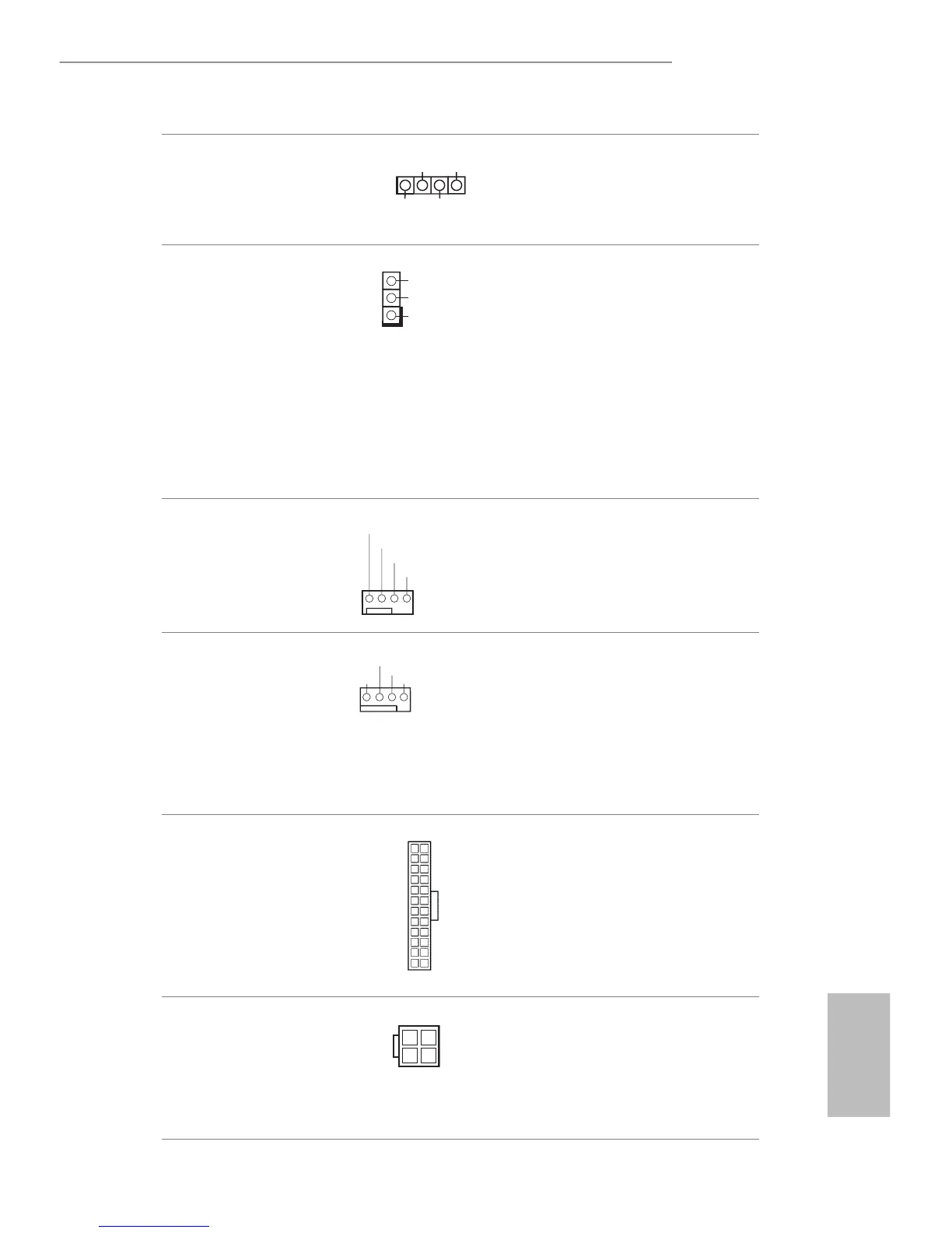
ATX Power Connector
(24-pin ATXPWR1)
(see p.5, No. 3)
is motherboard pro-
vides a 24-pin ATX power
connector. To use a 20-pin
ATX power supply, please
plug it along Pin 1 and Pin
13.
ATX 12V Power
Connector
(4-pin ATX12V1)
(see p.5, No. 18)
is motherboard
provides an 4-pin ATX
12V power connector.
 Loading...