22
22
2
ASRock N68PV-GS Motherboard
EnglishEnglish
EnglishEnglish
English
Motherboard LayoutMotherboard Layout
Motherboard LayoutMotherboard Layout
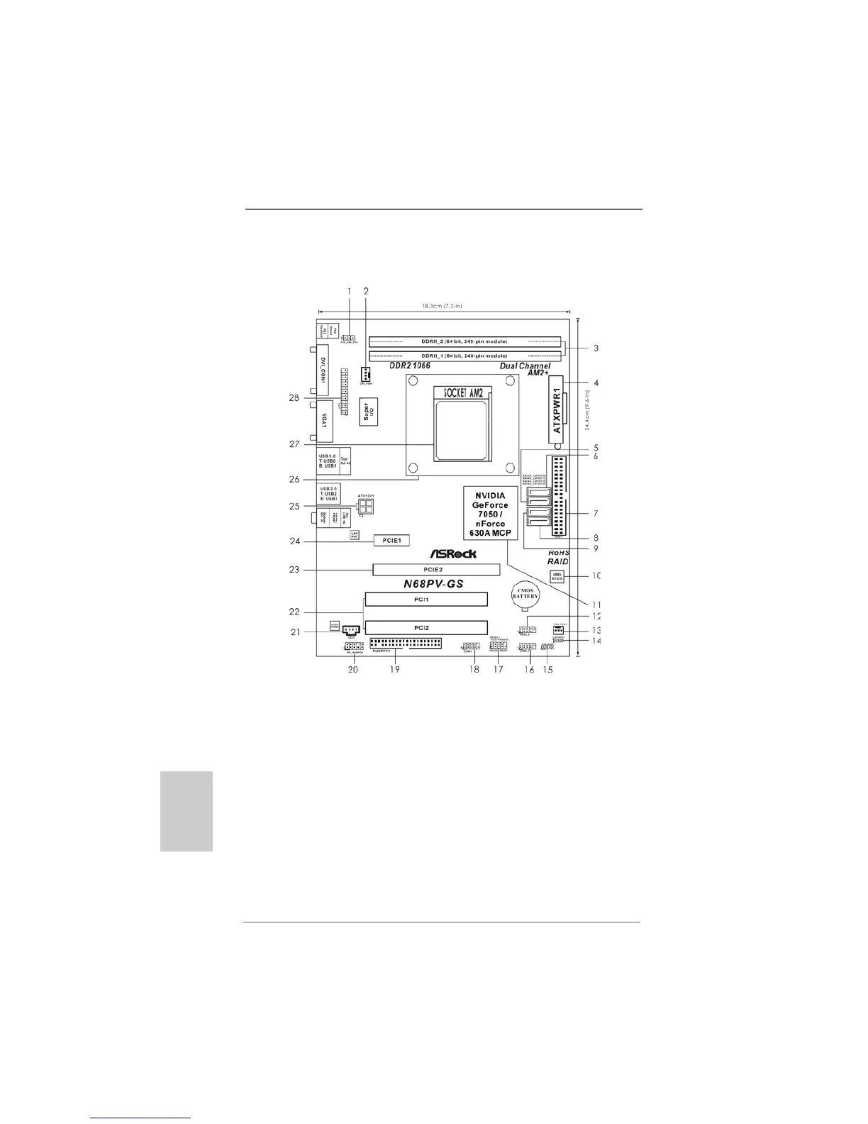
Motherboard Layout
1 PS2_USB_PW1 Jumper 16 USB 2.0 Header (USB6_7, Blue)
2 CPU Fan Connector (CPU_FAN1) 17 System Panel Header (PANEL1, Orange)
3 2 x 240-pin DDR2 DIMM Slots 18 Serial Port Connector (COM1)
(Dual Channel: DDRII_1, DDRII_2; Yellow) 19 Floppy Connector (FLOPPY1)
4 ATX Power Connector (ATXPWR1) 20 Front Panel Audio Header
5 Secondary SATAII Connector (SATAII_2 (PORT1)) (HD_AUDIO1, Lime)
6 Primary SATAII Connector (SATAII_1 (PORT0)) 21 Internal Audio Connector: CD1 (Black)
7 Primary IDE Connector (IDE1, Blue) 22 PCI Slots (PCI1- 2)
8 Fourth SATAII Connector (SATAII_4 (PORT3)) 23 PCI Express x16 Slot (PCIE2)
9 Third SATAII Connector (SATAII_3 (PORT2)) 24 PCI Express x1 Slot (PCIE1)
10 SPI Flash Memory (4Mb) 25 ATX 12V Power Connector (ATX12V1)
11 NVIDIA GeForce 7050 / nForce 630A MCP 26 CPU Heatsink Retention Module
12 USB 2.0 Header (USB4_5, Blue) 27 AM2 940-Pin CPU Socket
13 Chassis Fan Connector (CHA_FAN1) 28 Print Port Header (LPT1, Purple)
14 Clear CMOS Jumper (CLRCMOS1)
15 Chassis Speaker Header
(SPEAKER 1, Purple)
 Loading...