2828
2828
28
1
GND
+5 V
SPDIFOUT
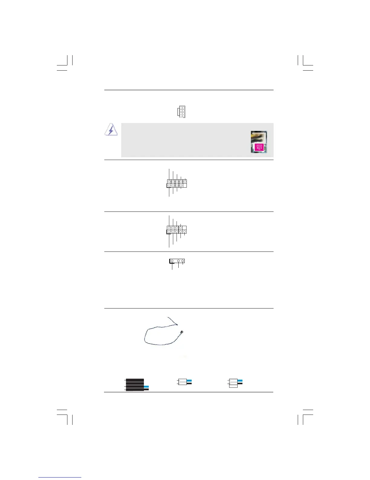
HDMI_SPDIF Header HDMI_SPDIF header, providing
(3-pin HDMI_SPDIF1) SPDIF audio output to HDMI VGA
(see p.11 No. 30 or p.12 No. 29) card, allows the system to
con nect HDMI Digital TV/
projector/LCD devices. Please
connect the HDMI_SPDIF
connector of HDMI VGA card to
this header.
HDMI_SPDIF Cable Please connect the black end (A)
(Optional) of HDMI_SPDIF cable to the
HDMI_SPDIF header on the
motherboard. Then connect the
white end (B or C) of
HDMI_SPDIF cable to the
HDMI_SPDIF connector of HDMI
VGA card.
A. black end B. white end (2-pin) C. white end (3-pin)
C
B
GND
+5 V
SPDIFOUT
blue
black
blue
black
GND
SPDIFOUT
A
ATX 12V Power Connector Please connect an ATX 12V
(8-pin ATX12V1) power supply to this connector.
(see p.11 No. 40 or p.12 No. 39)
IEEE 1394 Header Besides one default IEEE 1394
(9-pin FRONT_1394) port on the I/O panel, there is one
(see p.11 No. 23) IEEE 1394 header
(FRONT_1394) on this
motherboard. This IEEE 1394
header can support one IEEE
1394 port.
+12V
GND
+12V
1
RXTPBM_0
GND
RXTPAM_0
RXTPBP_0
GND
RXTPAP_0
4-Pin ATX 12V Power Supply Installation
Though this motherboard provides 8-pin ATX 12V power
connector, it can still work if you adopt a traditional 4-pin ATX
12V power supply. To use the 4-pin ATX power supply, please
plug your power supply along with Pin 1 and Pin 5.
Serial port Header This COM1 header
(9-pin COM1) supports a serial port module.
(see p.11 No.27 or p.12 No. 26)
CCTS#1
DDSR#1
DDTR #1
RRXD 1
DDCD #1
TTXD1
GND
RRTS #1
RRI#1
1
5 1
8 4
5 1
8 4



 To Next Page