Q1900B-ITX
/
D1800B-ITX
14 15
English
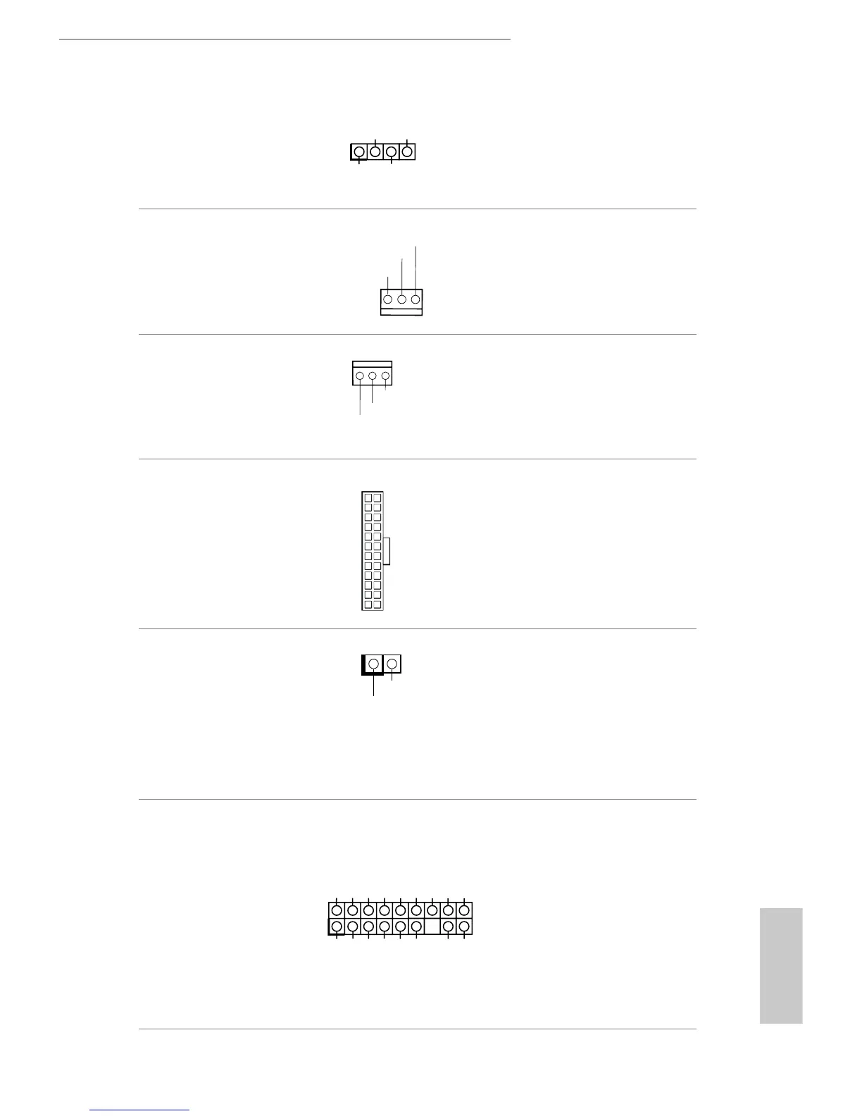
Chassis Speaker Header
(4-pin SPEAKER1)
(see p.7, No. 6)
Please connect the chassis
speaker to this header.
Chassis Fan Connector
(3-pin CHA_FAN1)
(see p.7, No. 11)
Please connect fan cable
to the fan connector and
match the black wire to
the ground pin.
CPU Fan Connectors
(3-pin CPU_FAN1)
(see p.7, No. 2)
Please connect the CPU
fan cable to the connector
and match the black wire
to the ground pin.
ATX Power Connector
(24-pin ATXPWR1)
(see p.7, No. 4)
is motherboard pro-
vides a 24-pin ATX power
connector. To use a 20-pin
ATX power supply, please
plug it along Pin 1 and Pin
13.
Chassis Intrusion Header
(2-pin CI1)
(see p.7, No. 12)
is motherboard supports
CASE OPEN detection feature
that detects if the chassis cove
has been removed. This feature
requires a chassis with chassis
intrusion detection design.
TPM Header
(17-pin TPMS1)
(see p.7, No. 1)
is connector supports Trusted
Platform Module (TPM) system,
which can securely store keys,
digital certicates, passwords,
and data. A TPM system also
helps enhance network security,
protects digital identities, and
ensures platform integrity.
GND
 Loading...