EasyManuals Logo

ASROCK Q1900TM-ITX User Manual

ASROCK Q1900TM-ITX
72 pages
To Next Page IconTo Next Page
To Previous Page IconTo Previous Page
Page #20 background imageLoading...
Page #20 background image
16
English
Front Panel Audio Header
(9-pin HD_AUDIO1)
(see p.5, No. 25)
is header is for
connecting audio devices
to the front audio panel.
Analog Surround
Audio Header
(17-pin HD_AUDIO2)
(see p.5, No. 28)
3W Audio AMP Output
Wafer Header
(4-pin SPEAKER1)
(see p.5, No. 27)
Please connect the chassis
speaker to this header.
12
PIN
Signal
Name
PIN
Signal
Name
18 SENSE 17 KEY
16 LFE 15 A_GND
14 A_GND 13 Center
12 Surr_Rear_R 11 A_GND
10 A_GND 9 Surr_Rear_L
8 Surr_Side_R 7 A_GND
6 A_GND 5 Surr_Side_L
4 Front_R 3 A_GND
2 A_GND 1 Front_L
Front_L+
Front_R-
Front_R+
Front_L-
1
1. High Denition Audio supports Jack Sensing, but the panel wire on the chassis must sup-
port HDA to function correctly. Please follow the instructions in our manual and chassis
manual to install your system.
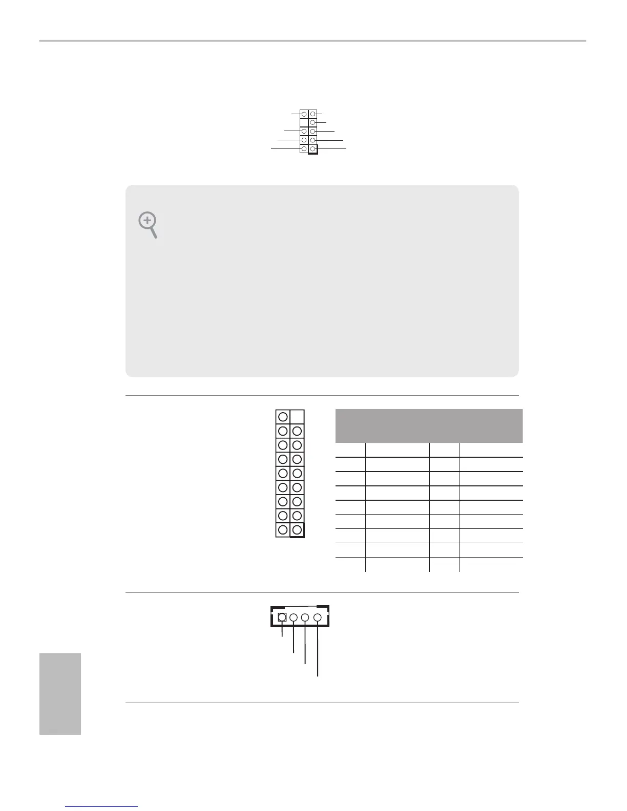
2. If you use an AC’97 audio panel, please install it to the front panel audio header by the
steps below:
A. Connect Mic_IN (MIC) to MIC2_L.
B. Connect Audio_R (RIN) to OUT2_R and Audio_L (LIN) to OUT2_L.
C. Connect Ground (GND) to Ground (GND).
D. MIC_RET and OUT_RET are for the HD audio panel only. You don’t need to connect
them for the AC’97 audio panel.
E. To activate the front mic, go to the “FrontMic” Tab in the Realtek Control panel and
adjust “Recording Volume”.
J_SENSE
OUT2_L
1
MIC_RED
OUT_RET
OUT2_R
MIC2_R
MIC2_L
GND
PRESENCE#

Other manuals for ASROCK Q1900TM-ITX

Questions and Answers:

Question and Answer IconNeed help?

Do you have a question about the ASROCK Q1900TM-ITX and is the answer not in the manual?

ASROCK Q1900TM-ITX Specifications

General IconGeneral
BrandASROCK
ModelQ1900TM-ITX
CategoryMotherboard
LanguageEnglish

Related product manuals