EasyManua.ls Logo

ASROCK ROMED6U-2L2T - User Manual

ASROCK ROMED6U-2L2T
2 pages
Print Icon
To Next Page IconTo Next Page
Loading...
ROMED6U-2L2T
Quick Installation Guide
www.asrockrack.com
2
Install the Server Board
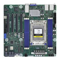
Motherboard Layout
The server board User's Manual is available for download from the ASRock Rack's o󰀩cial website
at http://www.asrockrack.com.
Take note of the following precautions before you install server board components or change any
server board settings.
1. Unplug the power cord from the wall socket before touching any components.
2. To avoid damaging the server board’s components due to static electricity, NEVER place your
server board directly on the carpet or the like. Also remember to use a grounded wrist strap or
touch a safety grounded object before you handle the components.
3. Hold components by the edges and do not touch the ICs.
4. Whenever you uninstall any component, place it on a grounded anti-static pad or in the bag
that comes with the component.
5. When placing screws into the screw holes to secure the server board to the chassis, please do
not over-tighten the screws! Doing so may damage the server board.
1
I/O Panel3
P/N: 15G065170000AK V1.0
*15G065170000AK*
1
Insert the server board into the chassis.
2
Affix the screws clockwise into the
mounting holes in all of the corners of
the server board.
Do not over-tighten the screws
No. Description
1 ATX 12V Power Connector (ATX12V2)
2 ATX 12V Power Connector (ATX12V1)
3 ATX 4-PIN Power Connector (ATX4PIN1)
4 PSU SMBus Header (PSU_SMB1)
5 PWM Conguration Header (PWM_CFG1)
6 System Fan Connector (FAN1)
7 System Fan Connector (FAN2)
8 System Fan Connector (FAN3)
9 System Fan Connector (FAN4)
10 System Fan Connector (FAN5)
11 System Fan Connector (FAN6)
12
3 x 288-pin DDR4 DIMM Slots (DDR4_E1, DDR4_
G1, DDR4_H1)
13
3 x 288-pin DDR4 DIMM Slots (DDR4_A1, DDR4_
C1, DDR4_D1)
14
SATA Power Connector (DC-IN Mode) (SATA-
PWR1)
15 M.2 Socket (M2_1) (Type 2280)
16 Slimline NVMe Connector (SLIM3)
17 Slimline NVMe Connector (SLIM2)
18 Slimline NVMe Connector (SLIM1)
(Right-Angled)
19 SATA3 Connector (SATA1)
20 Mini-SAS HD Connector (MSAS_HD0)
(Right-Angled)
21 Mini-SAS HD Connector (MSAS_HD1)
(Right-Angled)
22 Speaker Header (SPEAKER1)
23 System Panel Header (PANEL1)
24
Backplane PCI Express Hot-Plug Connector
(CPU1_HSBP1)
25 SATA SGPIO Connector (SATA_SGPIO3)
26 SATA SGPIO Connector (SATA_SGPIO2)
27 SATA SGPIO Connector (SATA_SGPIO1)
28 SATA3 Connector (SATA0)
29 Front LAN LED Connector (LED_LAN3_4)
30 USB 3.2 Gen1 Header (USB3_3_4)
(Right-Angled)
31 Clear CMOS Pad (CLRMOS1)
32 COM Port Header (COM1)
33 TPMS Header (TPMS1)
34 ermal Sensor Header (TR1)
35 Auxiliary Panel Header (AUX_PANEL1)
36 BMC SMBus Header (BMC_SMB1)
37
Intelligent Platform Management Bus Header
(IPMB_1)
38 Non Maskable Interrupt Button (NMI_BTN1)
39 M.2 Socket (M2_2) (Type 2260)
24.4cm (9.6 in)
VGA1
DDR4_G1 (64 bit, 288-pin module)
DDR4_H1 (64 bit, 288-pin module)
ATX12V2
USB 3.2 Gen1
T: USB2
B: USB1
IPMI_LAN
LAN3
UID1
PCIE7
M2_1
NUT80
HDLED RESET
PLED PWRBTN
PANEL1
1
1
SPEAKER1
1
T 1
R
1
IPMB_1
1
ASPEED
AST2500
ATX12V1
BMC
ROM
LGA4094
Socket SP3
PSU_SMB1
1
LAN4
DDR4_D1 (64 bit, 288-pin module)
DDR4_C1 (64 bit, 288-pin module)
FAN4
BATTERY1
ATX4PIN1
SATA_PWR1
PWM_CFG1
NMI_BTN1
24.4Cm (9.6 in)
12
3
4
56 8
9
10
11
12
13
14
15
16
17
2324262728
CLRMOS1
25
DDR4_E1 (64 bit, 288-pin module)
DDR4_A1 (64 bit, 288-pin module)
PCIE6
PCIE5
PCIE4
LAN1
LAN2
FAN3
FAN2
FAN1
FAN5
FAN6
SLIM3
SLIM2
SLIM1
MSAS_HD0
MSAS_HD1
Super
I/O
Intel
X710-AT2
Intel
I210-AT 2
Intel
I210-AT 2
1
SATA_SGPIO3
1
SATA_SGPIO2
1
SATA_SGPIO1
1
LED_LAN3_4
USB3_3_4
1
COM1
TPMS1
1
1
AUX_PANEL1
BMC_SMB1
ROMED6U-2L2T
BIOS
ROM
7
18
19
20
21
22303132 2933353637 3438
CPU_HSBP1
SATA0
SATA1
2
3
1
6
7
8
4
5
No. Description No. Description
1 UID Switch (UID1) 5 1G LAN RJ-45 Port (LAN4)
2 USB 3.2 Gen1 Ports (USB3_1_2) 6 VGA Port (VGA1)
3 LAN RJ-45 Port (IPMI_LAN1) 7 10G LAN RJ-45 Port (LAN1)
4 1G LAN RJ-45 Port (LAN3) 8 10G LAN RJ-45 Port (LAN2)
4 Power Connectors
ATX 12V Power
(ATX12V1/ATX12V2)
ATX 4-Pin Power (ATX4PIN1)
4
8
1
5
12V
GND
1
2
3
4
ATX_PWROK
PSON#
GND
ATX_+5VSB
M 2_2
39
NUT60_2
TOP VIEW BOTTOM VIEW
Question and Answer IconNeed help?

Do you have a question about the ASROCK ROMED6U-2L2T and is the answer not in the manual?

Overview

This document describes the ASRock Rack ROMED6U-2L2T server board, a high-performance component designed for robust server applications. It provides detailed instructions for installation, configuration, and maintenance, ensuring reliable operation within a server chassis.

Function Description

The ROMED6U-2L2T is a server motherboard that serves as the central hub for a server system. It supports a single LGA4094 Socket SP3 processor, indicating compatibility with AMD EPYC processors, which are known for their high core counts and extensive I/O capabilities, making it suitable for demanding workloads such as virtualization, data analytics, and high-performance computing. The board integrates essential components for server operation, including multiple DDR4 DIMM slots for memory, various PCIe slots for expansion cards, and a comprehensive set of I/O ports for connectivity. It also features an ASPEED AST2500 BMC (Baseboard Management Controller), which is crucial for remote server management, monitoring, and diagnostics, even when the main operating system is not running. This BMC functionality is a cornerstone of server reliability and ease of administration. The board's design emphasizes expandability and high-speed data transfer, with support for NVMe SSDs and multiple 10G LAN ports, catering to applications requiring fast storage and network throughput.

Important Technical Specifications

Processor Support:

  • Socket: LGA4094 Socket SP3, designed for AMD EPYC processors.
  • CPU: Supports a single processor configuration.

Memory:

  • Type: DDR4 DIMM slots.
  • Configuration: 6 x 288-pin DDR4 DIMM slots, divided into two groups (DDR4_E1, DDR4_G1, DDR4_H1 and DDR4_A1, DDR4_C1, DDR4_D1). This configuration supports a substantial amount of RAM, critical for memory-intensive server applications.
  • DIMM Installation: The manual provides a DIMM installation table for 1, 2, 4, and 6 DIMM configurations, indicating optimal slot usage for different memory capacities.

Storage:

  • SATA: 3 x SATA3 Connectors (SATA1, SATA0) and 3 x SATA SGPIO Connectors (SATA_SGPIO1, SATA_SGPIO2, SATA_SGPIO3). These provide ample connectivity for traditional hard drives and SSDs.
  • M.2 Sockets: 2 x M.2 Sockets (M2_1 Type 2280, M2_2 Type 2260) for high-speed NVMe SSDs.
  • Slimline NVMe: 3 x Slimline NVMe Connectors (SLIM1, SLIM2, SLIM3), with SLIM1 being right-angled, offering additional options for compact NVMe storage solutions.
  • Mini-SAS HD: 2 x Mini-SAS HD Connectors (MSAS_HDO, MSAS_HD1), both right-angled, for connecting multiple SAS/SATA drives via a single cable, often used with backplanes.

Expansion Slots:

  • PCIe: Multiple PCIe slots (PCIE4, PCIE5, PCIE6, PCIE7) for various expansion cards such as network adapters, HBAs, and GPUs.
  • Backplane Connector: Backplane PCI Express Hot-Plug Connector (CPU1_HSBP1), indicating support for hot-pluggable backplanes, enhancing serviceability.

Networking:

  • LAN Ports:
    • 2 x 10G LAN RJ-45 Ports (LAN1, LAN2) powered by Intel X710-AT2, providing high-speed network connectivity essential for data centers and high-bandwidth applications.
    • 2 x 1G LAN RJ-45 Ports (LAN3, LAN4), offering standard Gigabit Ethernet connectivity.
    • 1 x IPMI LAN RJ-45 Port (IPMI_LAN), dedicated for remote management.

I/O Ports (Rear Panel):

  • USB: 2 x USB 3.2 Gen1 Ports (USB3_1_2).
  • VGA: 1 x VGA Port (VGA1) for display output.
  • UID Switch: 1 x UID Switch (UID1) for system identification.

Internal Connectors:

  • Power:
    • 2 x ATX 12V Power Connectors (ATX12V1, ATX12V2).
    • 1 x ATX 4-PIN Power Connector (ATX4PIN1).
    • 1 x SATA Power Connector (DC-IN Mode) (SATA-PWR1).
  • Fan: 6 x System Fan Connectors (FAN1-FAN6) for robust cooling.
  • USB: 1 x USB 3.2 Gen1 Header (USB3_3_4) (Right-Angled).
  • Headers:
    • System Panel Header (PANEL1) for front panel controls and indicators.
    • Auxiliary Panel Header (AUX_PANEL1) for additional system status and control.
    • COM Port Header (COM1) for serial communication.
    • TPMS Header (TPMS1) for Trusted Platform Module support.
    • Thermal Sensor Header (TR1) for temperature monitoring.
    • Speaker Header (SPEAKER1).
    • Clear CMOS Pad (CLRMOS1) for resetting BIOS settings.
    • NMI Button (NMI_BTN1) for Non-Maskable Interrupt.
    • BMC SMBus Header (BMC_SMB1) and PSU SMBus Header (PSU_SMB1) for SMBus communication.
    • Intelligent Platform Management Bus Header (IPMB_1) for IPMB communication.
    • Front LAN LED Connector (LED_LAN3_4) for LAN status indicators.
    • PWM Configuration Header (PWM_CFG1) for fan control configuration.

BMC:

  • Controller: ASPEED AST2500, enabling comprehensive remote management capabilities.
  • BMC ROM: Dedicated BMC ROM for firmware.

Usage Features

Installation Procedures:

  • Server Board Installation: Detailed steps for inserting the server board into the chassis and securing it with screws, emphasizing not to overtighten.
  • Processor and Heatsink Installation: A multi-step process involving unscrewing torx screws, opening retention covers and brackets, installing the CPU with its carrier frame, and then securing the components. It specifically warns against separating the CPU from its carrier frame and recommends using a CPU installation tool to prevent pin bending.
  • PCIE Card Installation: Instructions for removing the bracket, aligning the card connector, pressing firmly, and securing the card with a screw.
  • Memory Installation: Clear steps for unlocking DIMM slots, inserting memory modules, and locking the clips.
  • M.2 SSD (NGFF) Module Installation: Guidance on preparing the module and screw, gently inserting the M.2 SSD into the slot, and tightening the screw, with a warning against overtightening.

Connectivity and Indicators:

  • LAN Port LED Indications: Comprehensive tables explaining the meaning of Activity/Link LED and Speed LED statuses for IPMI LAN, 1G LAN, and 10G LAN ports. This allows for quick visual diagnosis of network connectivity and speed.
    • IPMI LAN: Off (No Link), Blinking Yellow (Data Activity), On (Link) for Activity/Link; Off (10M bps connection or no link), Yellow (100M bps connection), Green (1Gbps connection) for Speed.
    • 1G LAN: Off (No Link), Blinking Green (Data Activity), On (Link) for Activity/Link; Off (10Mbps connection or no link), Yellow (100Mbps connection), Green (1Gbps connection) for Speed.
    • 10G LAN: Off (No Link), Blinking Yellow (Data Activity), On (Link) for Activity/Link; Off (100Mbps connection or no link), Yellow (1Gbps connection), Green (10Gbps connection) for Speed.

Safety Precautions:

  • Power Disconnection: Always unplug the power cord before handling components.
  • Static Electricity: Emphasizes using a grounded wrist strap or touching a grounded object, and never placing the server board on carpet to prevent damage from static electricity.
  • Component Handling: Instructs to hold components by their edges and avoid touching ICs.
  • Component Storage: Advises placing uninstalled components on a grounded anti-static pad or in their original bag.
  • Screw Tightening: Explicitly warns against overtightening screws to prevent damage to the server board.

Maintenance Features

Remote Management:

  • BMC (Baseboard Management Controller): The integrated ASPEED AST2500 BMC provides out-of-band management capabilities, allowing administrators to monitor server health, power cycle the server, update firmware, and troubleshoot issues remotely, even if the main operating system is unresponsive. The dedicated IPMI LAN port facilitates this functionality.
  • SMBus Headers: BMC SMBus Header (BMC_SMB1) and PSU SMBus Header (PSU_SMB1) allow for communication with other system components for monitoring and control.

Troubleshooting and Diagnostics:

  • LAN Port LEDs: The detailed LED indications for LAN ports are a primary diagnostic tool for network connectivity issues.
  • Clear CMOS Pad: The CLRMOS1 pad allows for easy resetting of BIOS settings, which can be useful for resolving configuration-related boot issues.
  • NMI Button: The NMI_BTN1 provides a way to trigger a Non-Maskable Interrupt, which can be used by system administrators or developers for debugging critical system failures.
  • Thermal Sensors: The Thermal Sensor Header (TR1) allows for additional temperature monitoring, aiding in proactive thermal management and preventing overheating.
  • Speaker Header: The SPEAKER1 header allows for connection of a system speaker, which can provide audible POST (Power-On Self-Test) codes for diagnosing boot problems.

Firmware Management:

  • BIOS ROM: The presence of a BIOS ROM indicates that the system's firmware can be updated, allowing for bug fixes, performance improvements, and support for new hardware.
  • BMC ROM: A dedicated BMC ROM ensures that the BMC firmware can also be independently updated, enhancing its functionality and security.

Expandability and Serviceability:

  • Hot-Plug Backplane Support: The Backplane PCI Express Hot-Plug Connector (CPU1_HSBP1) indicates support for hot-pluggable backplanes, which simplifies drive replacement and maintenance without requiring a full system shutdown.
  • Modular Design: The clear layout and distinct connectors for various components (fans, power, storage, expansion cards) facilitate easy access for upgrades, replacements, and maintenance.

Documentation:

  • User's Manual: The availability of a detailed User's Manual on the ASRock Rack website (http://www.asrockrack.com) provides comprehensive information beyond the quick installation guide, essential for in-depth configuration and troubleshooting.

ASROCK ROMED6U-2L2T Specifications

General IconGeneral
BrandASROCK
ModelROMED6U-2L2T
CategoryComputer Hardware
LanguageEnglish

Related product manuals