Do you have a question about the ASROCK N100DC-ITX and is the answer not in the manual?
Lists items included with the ASRock N100DC-ITX motherboard.
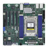
Details platform, CPU, memory, expansion slot, graphics, audio, LAN, USB, and rear panel I/O.
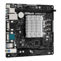
Visual guide showing the placement of components on the motherboard.
Describes rear panel connectors and functions, including LED indicators.
Illustrates the internal architecture and data flow of the motherboard.
Safety guidelines before installing components or changing settings.
Instructions for installing a DDR4 DIMM into the slot.
Guide to connecting front panel wires to the system panel header.
Instructions on how to install the I/O panel shield.
Steps for mounting the motherboard into the computer chassis.
Guide for connecting SATA drives to the motherboard and power supply.
Instructions for installing an expansion card like a graphics card.
Details about the PCIe slot and its usage for graphics cards.
Shows how to connect common peripherals like mouse, keyboard, monitor, speakers.
Steps to power on the system after installation.
Explanation of jumper settings, specifically Clear CMOS Jumper (CLRMOS1).
Details on System Panel Header (PANEL1) and its pins.
Instructions for connecting chassis intrusion and speaker to the header.
Details on SATA3 connectors (SATA3_0, SATA3_1) for data transfer.
Details on USB 2.0 headers and their port configurations.
Information about the USB 3.2 Gen1 header and its ports.
Guide for connecting audio devices to the front audio panel.
Instructions for connecting chassis fan cables to the motherboard.
Details about the SPI TPM Header for security module connection.
Instructions for connecting a SATA power cable.
Steps for installing an Intel CNVi (WiFi/BT) module in the M.2 slot.
Guide for installing an M.2 SSD module into the M.2 slot.
| Form Factor | Mini-ITX |
|---|---|
| Memory Slots | 2 x SO-DIMM |
| Audio | Realtek ALC897 Audio Codec |
| USB Ports | 4 x USB 3.2 Gen1, 2 x USB 2.0 |
| Expansion Slots | 1 x PCIe 3.0 x16 |
| Video Outputs | 1 x HDMI, 1 x DisplayPort |
| Processor | Intel Processor N100 Series |
| Maximum Memory | 32GB |
| Storage Interface | 1 x M.2 |
| Graphics | Intel UHD Graphics |
| Network | 1 x Gigabit LAN |
| Power Supply | 19V DC-in |