ROMED8-2T
Quick Installation Guide
www.asrockrack.com
4
2
P/N: 15G065153000AK V1.0
Install the Server Board
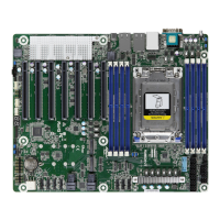
Motherboard Layout
Jumper Settings (PE8_SEL / PE16_SEL)
The server board User's Manual is available for download from the ASRock Rack's ocial website
at http://www.asrockrack.com.
Take note of the following precautions before you install server board components or change any
server board settings.
1. Unplug the power cord from the wall socket before touching any components.
2. To avoid damaging the server board’s components due to static electricity, NEVER place your
server board directly on the carpet or the like. Also remember to use a grounded wrist strap or
touch a safety grounded object before you handle the components.
3. Hold components by the edges and do not touch the ICs.
4. Whenever you uninstall any component, place it on a grounded anti-static pad or in the bag
that comes with the component.
5. When placing screws into the screw holes to secure the server board to the chassis, please do
not over-tighten the screws! Doing so may damage the server board.
1
1
Insert the server board into the chassis.
2
Ax the screws clockwise into the mounting holes in
all of the corners of the server board.
Do not over-tighten the screws
When the jumper cap is placed on the pins,
the jumper is “Short”. If no jumper cap is
placed on the pins, the jumper is “Open”.
e illustration shows a 3-pin jumper whose
pin1 and pin2 are “Short” when a jumper cap
is placed on these 2 pins.
I/O Panel3
2
3
1
4
5
6
7
8
Remove the standoff
from the chassis
Rear I/O
Attention! Before installing this motherboard, be sure to
unscrew and remove the standos at the marked location,
under the motherboard, from the chassis, in order to avoid
electrical short circuit and damage to your motherboard.
*15G065153000AK*
No. Description No. Description
1 UID Switch (UID1) 5 LAN RJ-45 Port (IPMI_LAN1)
2 VGA Port (VGA1) 6 10G LAN RJ-45 Port (LAN1)
3 Serial Port (COM1) 7 10G LAN RJ-45 Port (LAN2)
4 USB 3.1 Gen1 Ports (USB3_1_2) 8 USB 3.1 Gen2 Port (USB31_TC_1)
PE8_SEL PE16_SEL PCIE2 M2_1 SATA_4_7
OCU1 &
OCU2
O X X X
O O O X
X O O O
X X X O
(x16)
(x8)
24.4cm (9.6 in)
30.5cm (12.0 in)
ATXPWR1
2
VGA1
COM1
DDR4_D1 (64 bit, 288-pin module)
DDR4_C1 (64 bit, 288-pin module)
DDR4_B1 (64 bit, 288-pin module)
DDR4_A1 (64 bit, 288-pin module)
DDR4_E1 (64 bit, 288-pin module)
DDR4_F1 (64 bit, 288-pin module)
DDR4_G1 (64 bit, 288-pin module)
DDR4_H1 (64 bit, 288-pin module)
ATX 12V1
PCIE6
PCIE7
3
4
5
7
USB 3.1 Gen1
T: USB2
B: USB1
IPMI_LAN
LAN1
LAN2
UID1
USB3_3_4
OCU1
OCU2
SATA_0_3
SATA_4_7
GFX_12V1
PCIE4
PCIE5
PCIE2
PCIE3
PCIE1
M2_2
M2_1
NUT30
NUT42
NUT60
NUT80
NUT30_2
NUT42_2
NUT60_2
NUT80_2
BAT1
1
AUX_PANEL1
HDLED RESET
PLED PWRBTN
PANEL1
1
1
TPM1
1
SPEAKER1
1
T 1
R
1
1
IPMB1
NMI_BTN1
1
CHASSIS_ID0
1
BMC_SMB_1
AST
2500
RoHS
ROMED8-2T
ATX 12V2
FAN1
FAN2
FAN3
FAN4
FAN5
FAN7
BMC
F/W
8
9
10
11
12
14
15
16
18
19
22
23
242829
30
33
31
36
37
38
40
41
Intel
X550
LGA4094
Socket SP3
34
CLRMOS1
35
1
PSU_SMB1
1
NUT110_2
Dr.
Debug
(NCSI)
17
FAN6
25
USB31_TC_1
USB31_TC_2
USB3.1 Gen2
13
1
1
PE16_SEL
PE8_SEL
27 26
1
TPM_BIOS_ PH1
1
NV12V_2
1
NV12V_4
1
NV12V_3
1
NV12V_1
1
T 1B
6
20
21
39
42
43
CPU1_HSBP1
32
1 PSU SMBus Header (PSU_SMB1)
2 ATX 12V Power Connector (ATX12V1)
3 ATX 12V Power Connector (ATX12V2)
4 ATX Power Connector (ATXPWR1)
5 USB 3.1 Gen1 Header (USB3_3_4)
6 NVDIMM Power Support Jumper (NV12V_1)
7 NVDIMM Power Support Jumper (NV12V_3)
8 System Fan Connector (FAN1)
9 System Fan Connector (FAN2)
10 OCuLink x4 Connector (OCU1)
11 System Fan Connector (FAN3)
12 OCuLink x4 Connector (OCU2)
13 M.2 Socket (M2_2) (Type 2230 / 2242 / 2260 / 2280 / 22110)
14 M.2 Socket (M2_1) (Type 2230 / 2242 / 2260 / 2280)
15 Mini-SAS HD Connector (SATA_0_3)
16 Mini-SAS HD Connector (SATA_4_7)
17 System Fan Connector (FAN4)
18 System Fan Connector (FAN5)
19 System Fan Connector (FAN6)
20 System Fan Connector (FAN7)
21 Graphics 12V Power Connector (GFX_12V1)
22 Speaker Header (SPEAKER1)
23 System Panel Header (PANEL1)
24 Auxiliary Panel Header (AUX_PANEL1)
25 Clear CMOS Pad (CLRMOS1)
26 PCIE2 x16 Selection Jumper (PE16_SEL)
27 PCIE2 x8 Selection Jumper (PE8_SEL)
28 ermal Sensor Header (TR1)
29 TPM Header (TPM1)
30 BMC SMBus Header (BMC_SMB1)
31 Intelligent Platform Management Bus Header (IPMB1)
32 CPU HP-SMBus Connector (CPU1_HSBP1)
33 Non Maskable Interrupt Button (NMI_BTN1)
34 underbolt AIC Connector (TB1)*
35 Chassis ID Jumper (CHASSIS_ID0)
36 Front Panel Type C USB 3.1 Gen2 Header (USB31_TC_2)
37 2 x 288-pin DDR4 DIMM Slots (DDR4_B1, DDR4_D1)**
38 2 x 288-pin DDR4 DIMM Slots (DDR4_A1, DDR4_C1)**
39 TPM-SPI Header (TPM_BIOS_PH1)
40 2 x 288-pin DDR4 DIMM Slots (DDR4_E1, DDR4_G1)**
41 2 x 288-pin DDR4 DIMM Slots (DDR4_F1, DDR4_H1)**
42 NVDIMM Power Support Jumper (NV12V_4)
43 NVDIMM Power Support Jumper (NV12V_2)