EasyManua.ls Logo

Assa Abloy EffEff 1340-14 User Manual

Assa Abloy EffEff 1340-14
76 pages
Go to English
To Next Page IconTo Next Page
Page #1 background imageLoading...
Page #1 background image
Experience a safer
and more open worldDXXXXXNN
Installations- und Montageanleitung
Produktname
Produktname
assaabloyopeningsolutions.de
Experience a safer
and more open world
Installations- und Montageanleitung
N
O
T
A
U
F
DE Seite 2
EN Page 38
Fluchttür-Steuerterminal
1340-14/-15/-20/-21
Fluchttür-Steuerterminal
D0131500

Table of Contents

Other manuals for Assa Abloy EffEff 1340-14

Question and Answer IconNeed help?

Do you have a question about the Assa Abloy EffEff 1340-14 and is the answer not in the manual?

Assa Abloy EffEff 1340-14 Specifications

General IconGeneral
BrandAssa Abloy
ModelEffEff 1340-14
CategoryControl Systems
TypeElectric Strike
Fail-secure or Fail-safeFail-secure
Adjustable latch bolt (FF)Yes
Operating Temperature-15°C to +40°C
IP RatingIP54
Locking DirectionUniversal
MaterialSteel
Operating voltage12/24 VDC
MountingSurface

Summary

Comprehensive Safety Instructions

Electrical Safety and Handling

Contact with live parts is life-threatening; only certified electricians should open.

Product Integrity and Modification Risks

Safety features are essential; unauthorized changes are prohibited.

Operational Safety (Commissioning, Maintenance, Repairs)

Proper commissioning, maintenance, and qualified repairs are critical for safety.

Regulatory Compliance and Building Authority Rules

Adherence to building regulations and inspectorate requirements is mandatory.

Intended Use and Application

Commercial Sector Application and Conformity

For escape routes in commercial sector, tested to EltVTR; non-approved uses forbidden.

Mounting Variants and Installation Requirements

Surface vs. flush mounting suitability; requires certified installer.

Authority Coordination and Usage Compliance

Usage must align with building inspectorate requirements and safety concepts.

The 1340 Escape Door Control Terminal

General Functionality Overview

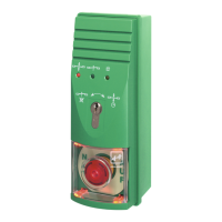
Controls and monitors a single escape door; integrates all control electronics.

Model 1340-20/-21: Power and Connectivity

No integrated power supply; requires external power; can be stand-alone or bus devices.

Model 1340-14/-15: Stand-alone Operation

For stand-alone operation; same functionality as 1340-20/-21 but without bus support.

Model Specifications and Characteristics

1340-14/-15 Stand-alone Features

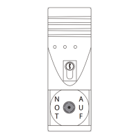
Stand-alone operation, integrated emergency button, external release, permanent/temporary release options.

1340-20/-21 Operation Modes

Operates in two modes: stand-alone (mode 1) or bus participant (mode 2).

Mode 1: Stand-alone Functionality

Terminal controls/monitors door; operation via terminal or external panel.

Mode 2: Bus Participant Functionality

Terminal acts as bus participant on door control bus; DCB controller enables central control.

Mounting Procedures and Requirements

Mounting Regulations and Placement

EMERGENCY OPEN button height 850-1200mm; comply with local ordinances.

Mounting Preparations and Guidelines

Installation Preparatory Tasks

Install near door; surface or flush mount; route supply lines through bushings.

Cable Selection Criteria

Max cable length 300m (control), 100m (locking); select cross-section for voltage drop.

Connectible Locking Elements

Connection details in D00470xx; permissible combinations in test certificate.

Housing Access and Component Removal

Procedure for Opening the Housing

Steps include switching off power, removing cover/sticker, loosening screws, disconnecting ribbon cable.

Wall Mounting Options and Installation

Surface Mounting Installation

Remove upper part, drill holes using jig, screw lower part, replace upper part.

Component Replacement Procedures

Profile Cylinder Replacement Steps

Configuration Overview and Wiring

Terminal Configuration Settings

DIP Switch Configuration Options

Rotary Switch Configuration Settings

Bus Operation Mode Configuration

Bus Address Configuration Details

Set-up and Commissioning Procedures

Core Operational Functions

Permanent Release and Locking Operations

Alarm Monitoring and Handling

Fire Alarm System Integration

Connecting the Fire Alarm System

Connect to terminals 13/14; door unlocks immediately on fire alarm.

Important Notes on Fire Alarm Malfunction

Terminals 13/14 need jumper if no fire alarm; acknowledge/reset via fire alarm system.

Alarm Conditions and Causes

Alarm Management and Troubleshooting

Technical Specifications (12V System)

Technical Specifications (24V System)

Pre-Operation Testing and Checks

Related product manuals