23
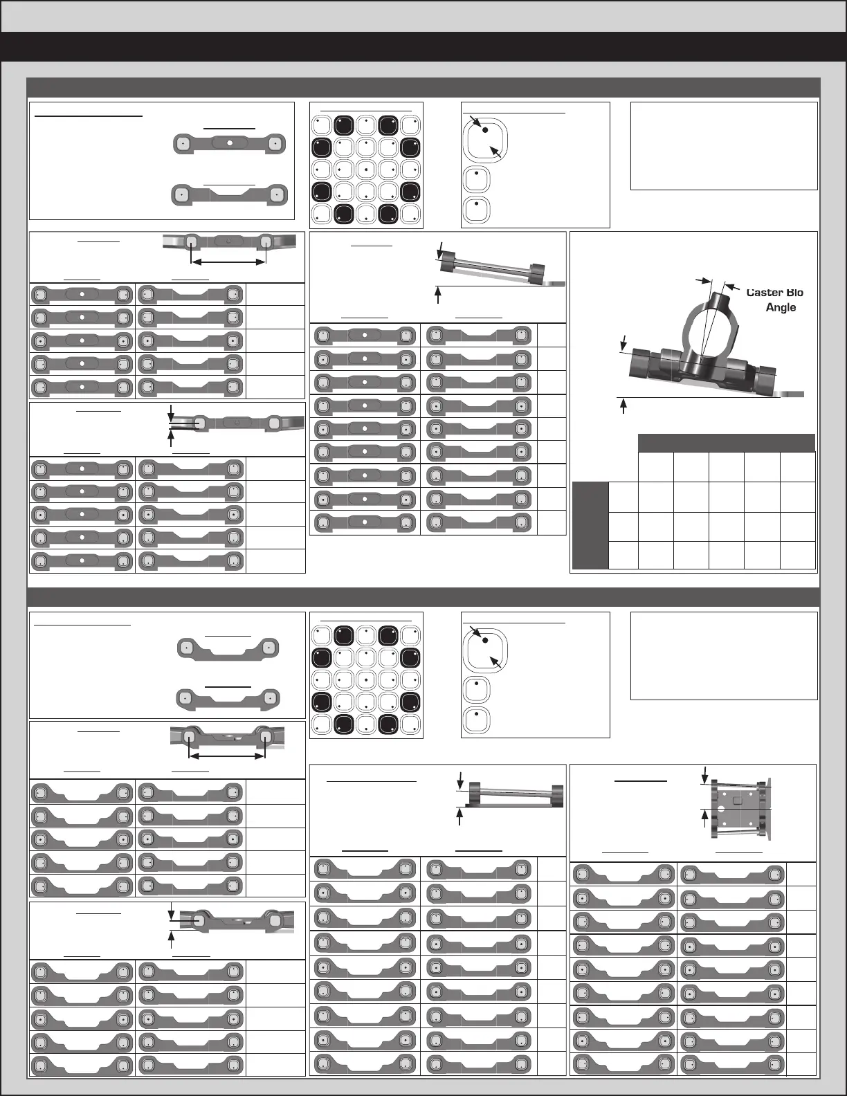
:: Tuning Tips - Front Arm Mount Pill Insert Setups:: Tuning Tips - Front Arm Mount Pill Insert Setups
:: Tuning Tips - Rear Arm Mount Pill Insert Setups:: Tuning Tips - Rear Arm Mount Pill Insert Setups
The aluminum front arm mounts
utilize eccentric pill inserts to make
fi ne adjustments to kick-up, pin
height, and pin width. Adjustments
can be made using the supplied
inserts (#92014)
The aluminum front arm mounts
utilize eccentric pill inserts to make
fi ne adjustments to kick-up, pin
height, and pin width. Adjustments
can be made using the supplied
inserts (#92014)
Standard Position
A Mount
B Mount
Use this position as
a reference when
changing pill locations.
Kick-up: 8°
Roll Center: +0
Pin Width: +0
Insert Hole Locations
Hole 0.5° or 0.35mm
from center
Hole 1.0° or 0.7mm
from center
Number indicates
degree of change:
0.5°,1.0°, 0° (center dot)
.5
1
1
Insert Hole Locations
Hole 0.5° or 0.35mm
from center
Hole 1.0° or 0.7mm
from center
Number indicates
degree of change:
0.5°,1.0°, 0° (center dot)
.5
1
1
Pin Width
A Mount B Mount
= +1.4mm
= +0.7mm
= 0mm
= -0.7mm
= -1.4mm
More distance = wider pivot
Less distance = narrower pivot
.5
.5
.5
.5
.5
.5
.5
.5
1
1
1
1
1
1
1
1
Pin Height
A Mount B Mount
= +0.7mm
= +0.35mm
= 0mm
= -0.35mm
= -0.7mm
Higher pin = Higher roll center
Lower Pin = Lower roll center
.5
.5
.5
.5
.5
.5
.5
.5
1
1
1
1
1
1
1
1
Standard Position
C Mount
D Mount
Use this position as
a reference when
changing pill locations.
Toe: 3°
Anti-Squat: 2°
Roll Center: +0
Pin Width: +0
Pin Width
C Mount D Mount
= +1.4mm
= +0.7mm
= 0mm
= -0.7mm
= -1.4mm
More distance = wider pivot
Less distance = narrower pivot
.5
.5
.5
.5
.5
.5
.5
.5
1
1
1
1
1
1
1
1
Pin Height
C Mount D Mount
= +0.7mm
= +0.35mm
= 0mm
= -0.35mm
= -0.7mm
Higher pin = Higher roll center
Lower Pin = Lower roll center
.5
.5
.5
.5
.5
.5
.5
.5
1
1
1
1
1
1
1
1
Toe Angle
C Mount D Mount
= 3°
= 4°
= 5°
= 2°
= 3°
= 4°
= 1°
= 2°
= 3°
More angle = More toe in
Less angle = Less toe in
Shown in
1° changes
111
111
1 1 1
1 1 1
1 1 1
1 1 1
111
111
Anti-Squat Angle
C Mount D Mount
= 2°
= 1°
= 0°
= 3°
= 2°
= 1°
= 4°
= 3°
= 2°
More angle = More anti-squat
Less angle = Less anti-squat
Shown in
1° changes
1
1
1
1
1
1
1
1
1
1
1
1
1
1
1
1
1
1
1
1
1
1
1
1
Kick Up
A Mount B Mount
= 8°
= 7°
= 6°
= 9°
= 8°
= 7°
= 10°
= 9°
= 8°
More angle = More kick up
Less angle = Less kick up
Shown in
1° changes
1
1
1
1
1
1
1
1
1
1
1
1
1
1
1
1
1
1
1
1
1
1
1
1
Total caster angle is the sum of the kick
up angle and the caster block angle.
Total Caster Angle
Caster Block
Angle
Kick Up
Angle
10°6° 7° 8° 9°
18°14°8° 15° 16° 17°
19°15°9° 16° 17° 18°
20°16°10° 17° 18° 19°
Kick Up AngleKick Up Angle
Caster BlockCaster Block
Angle Angle
.5
.5
.5
.5
.5
.5
.5
.5
1
1
1
1
1
1
1
1
Possible Insert Locations
1/.5
1/.5
1/.5
1/.5
1/.5
1/.5
1/.5
1/.5
.5
.5
.5
.5
.5
.5
.5
.5
1
1
1
1
1
1
1
1
Possible Insert Locations
1/.5
1/.5
1/.5
1/.5
1/.5
1/.5
1/.5
1/.5