IB-2003 Series 40 Transfl ite - Stationary Conveyor
33
Conveyor Set-up
After all parts have been
unloaded, inspect each item
for damage and report any
damaged or missing items to
the carrier.
Fasteners found in the
hardware box will be grouped
and marked to indicate use.
In some cases they will also
be marked with a specifi c job
number.
The conveyor can be
assembled using the following
procedure.
Frame Sections
Many conveyor frames are
shipped as one piece; however,
on longer conveyors it will
be necessary to assemble
conveyor frame sections
together.
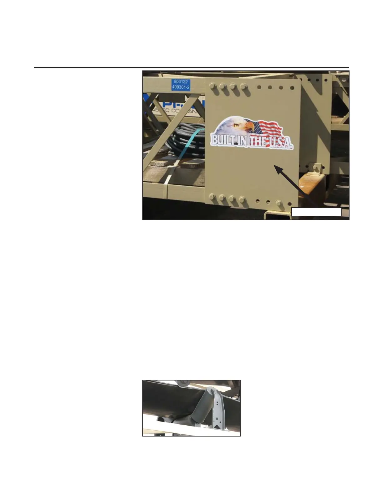
1. Align conveyor section
joining plates so bolt holes
align.
2. Locate frame section
prevailing torque locknuts in
the hardware box. Align
holes and locknuts loosely.
When all locknuts have
been installed, they should
be tightened.
See Appendix B for bolt torque
information
Belt Idlers
Belt idlers are installed at
the factory; however, special
orders may indicate idlers
removed for shipment.
Use the following procedure to
install idlers.
1. Locate idler fasteners in the
hardware box.
2. Place troughing idlers along
the top of the conveyor
frame and bolt loosely.
Troughing Idler
Connector plate
3. Slide the idlers to the end
of the slot toward the tail
end and tighten.
If installing self-aligning idlers,
use the belt travel direction
marking to properly install.
When installing the return
idlers, procedure is the same
as installing the troughing
idlers.