IB-2003
eries 40 Trans
ite -
tationary
onveyor
34
Set-up
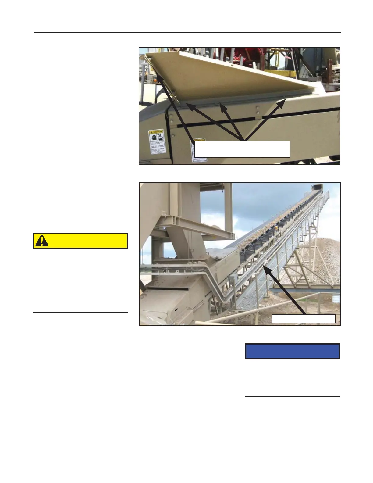
Receiving Hopper (optional)
Assemble the optional receiving
hopper to the conveyor as
shown in the picture to the
right. Bolt the receiving hopper
to the tail end.
Assembly of the electrical
wiring can be done with a
cable tray.
1. Secure wire along the
conveyor frame and wire
in to the conveyor drive
motor.
2. Connect power to conveyor
drive.
3. Check the motor for proper
rotation before installing
Operating the conveyor
drive backward can cause
damage to the reducer,
backstop and motor.
Electrical
When the conveyor has been
assembled, the electrical
wiring can be completed.
Installation and maintenance
of electrical devices must
comply with all applicable
codes and regulations and
must be done by a qualifi ed
electrical contractor.
NOTICE
CAUTION
Assembling Receiving Hopper to Conveyor
Hopper is bolted to conveyor in
four places on each side.
Drives
Reducers are shipped from the
factory fi lled with oil; however,
check the oil level in the
reducers and fi ll if necessary.
drive belts. Rotation
direction is typically marked
on the motor housing or
guard.
On drives with v-belts installed,
it will be necessary to relieve
belt tension enough to allow
belts to slip when checking
drive rotation.
Relieve tension on reducer
v-belt by loosening motor
mount nuts. Turn nuts as far
as possible. Do not loosen
top nuts.
Cable Tray Installed on Conveyor
Electrical cable tray
 Loading...