Viron Pool and Spa Heater Page 9
INSTALLATION
THIS APPLIANCE MUST BE INSTALLED BY AN AUTHORISED PERSON. Refer to heater
data plate for specifications of gas type, gas consumption, burner pressure and water pressure.
This appliance must be installed in accordance with local regulations and Australian Standard
Installation Code AS5601.
The installer must test the operation of the appliance before leaving.
FLOW RATES
The Viron Pool Heater requires a minimum of 250 litres per minute flow and the maximum
permissible flow rate is 500 litres per minute. For flow rates in excess of 600 litres per minute, an
external by-pass valve must be fitted.
WATER CONNECTIONS
The heater should always be installed after the pump and filter. The water connections are located
on the right hand side of the heater. The inlet and outlet are clearly marked. Water connections
require 50 mm PVC glue in plumbing.
All automatic sanitising devices must be installed after the heater and in such a way that the
sanitiser cannot enter the heater without first mixing with the water in the pool or spa. Sanitisers
that are connected prior to the heater will void heater warranty.
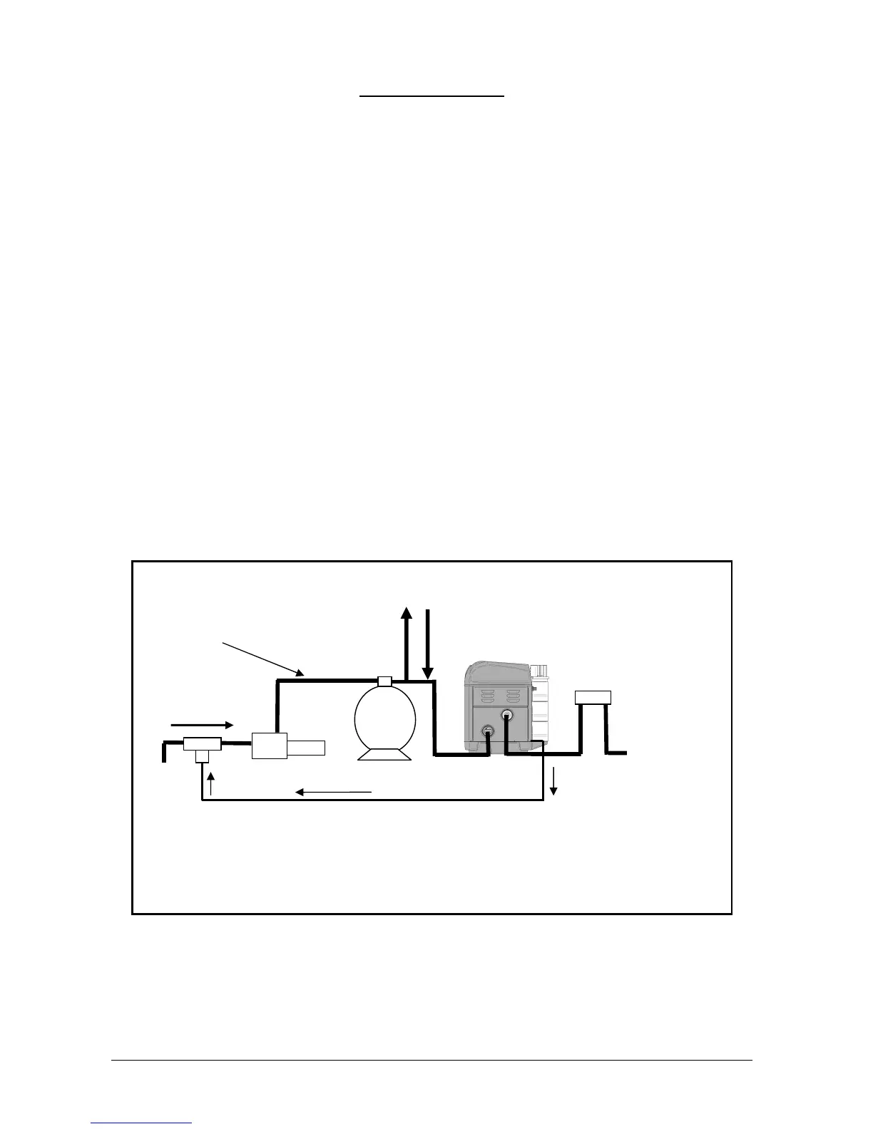
PLUMBING DIAGRAM
Condensation Drain Hose (optional)
To Solar
From Solar
From Pool
Pump
Filter
Heater
Chlorinator
Return to Pool
Heater Diagram
1. Plumbing in high pressure 50mm PVC pipe
2. Connection to heater in Class 12 or higher
3. All automatic Chlorinators or Sanitisers Must be installed after heater





 To Next Page