The Astro Tool Corp. AMT4001 (M22520/40-1) is a precision crimp tool designed for connector assembly, specifically for crimping insulated terminals, splices, and endcaps. This manual provides detailed instructions for its use, technical specifications, and maintenance.
Function Description
The AMT4001 crimp tool is engineered to create reliable electrical connections by securely crimping various types of insulated terminals, splices, and endcaps. It is designed to work with components manufactured to AS7928 (MIL-T-7928) standards, including AS25036 (MS25036), AS17143 (MS17143), and AS25274 (MS25274). The tool features color-coded handles and crimp cavities to facilitate matching the correct cavity with the color-coded terminal, splice, or endcap being crimped. This color-coding system is also detailed on the tool's side plate for easy reference.
A key feature of the AMT4001 is its adjustable insulation crimp cavity. This cavity can be set to one of four height settings, allowing for adaptability based on the insulation diameter of the terminal, splice, or endcap and the wire being crimped. This adjustability ensures a proper grip on the wire insulation, preventing pull-out and ensuring a secure connection.
The tool incorporates spring-loaded locators that assist in accurately positioning the terminals, splices, or endcaps within the crimp cavity. This feature helps to ensure consistent and precise crimps. Furthermore, the AMT4001 is equipped with a tamper-proof double-action ratchet mechanism. Once engaged, this ratchet will not release until the handles are fully closed and the crimp operation is completed, guaranteeing a full and proper crimp cycle every time.
Important Technical Specifications
The AMT4001 is designed for specific wire sizes and crimp areas, as detailed in the gaging section of the manual. The tool utilizes various Astro Part Numbers for gaging, each corresponding to a specific MS Part Number, wire size (AWG), and gage area.
- M22520/43-01 (AMTG4301): GO/NO-GO gage for 22-16 AWG, Red Conductor Cavity.
- M22520/43-02 (AMTG4302): GO/NO-GO gage for 16-14 AWG, Blue Conductor Cavity.
- M22520/43-03 (AMTG4303): GO/NO-GO gage for 22-16 AWG, Red Insulation Cavity.
- M22520/43-04 (AMTG4304): GO/NO-GO gage for 16-14 AWG, Blue Insulation Cavity.
These specifications highlight the tool's precision and the need for appropriate gaging to maintain its performance. The insulation crimp adjustment allows for fine-tuning based on insulation diameter, ensuring optimal performance across a range of applications within the specified wire sizes.
Usage Features
The usage of the AMT4001 involves a straightforward crimping procedure and a specific method for adjusting the insulation crimp.
Crimping Procedure:
- Wire Preparation: Strip the wire to the dimension specified by the terminal, splice, or endcap manufacturer.
- Tool Opening: If the die cavity is not open, close the tool handles until the ratchet releases and the die cavity opens.
- Component Placement: Place the color-coded terminal, splice, or endcap into the proper cavity of the crimp dies. Ensure the terminal tongue slides under the locator, the splice window slides under the locator, or the endcap end rests against the recess in the locator.
- Initial Closure: Close the tool handles until the component is held in place but not yet crimped.
- Wire Insertion: Insert the stripped wire into the terminal until the conductor butts against the locator. For splices or endcaps, insert the stripped wire until the conductor butts against the internal stop.
- Complete Crimp: Hold the wire in position and fully close the handles until the ratchet releases, completing the crimp.
- Splice Specific: If crimping a splice, rotate it 180 degrees and repeat steps 3-6 to ensure a complete crimp.
Insulation Crimp Adjustment:
The tool has four insulation crimp positions. To set the insulation crimp height:
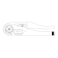
- Loosen Screw: Loosen the insulation adjustment locking screw and turn the indicator to position 4 (as shown in Figure 1).
- Load Component: Load the terminal or splice into the crimp cavity.
- Insert Un-stripped Wire: Insert an un-stripped wire only into the insulation barrel of the terminal or splice.
- Perform Crimp: Perform a crimp and remove the crimped component.
- Check Wire Grip: Bend the wire back and forth once. The terminal or splice should retain a grip on the wire insulation.
- Adjust if Necessary: If the wire pulls out, adjust to the next descending insulation crimp position.
- Recheck: Perform another crimp and recheck the wire grip.
- Repeat: Repeat the adjustment as necessary until the wire is gripped. It is crucial not to use a tighter setting than required.
- Retighten Screw: Retighten the insulation adjustment locking screw.
Maintenance Features
Proper maintenance and periodic inspection are crucial for ensuring the AMT4001's dependable and uniform terminations. Astro Tool Corp. strongly recommends specific practices and offers services to support the tool's longevity and performance.
Inspection and Gaging:
Astro recommends periodic inspection and gaging of the tool. The frequency of these checks depends on several factors:
- Care and Use: The level of care, amount of use, and handling of the tool.
- Product Type and Size: The type and size of products being crimped.
- Operator Skill: The degree of operator skill.
- Environmental Factors: The presence of abnormal amounts of dust and dirt.
- User Standards: The user's own established standards.
Gaging the Crimp Cavities (Conductor and Insulation):
Conductor Cavity Gaging:
- Close Handles: Close the tool handles fully and hold them firmly.
- Insert GO Gage: Insert the appropriately sized GO gage (Green) member under the locator and into the conductor cavity of the die (Red or Blue) being gaged. The GO gage member should freely enter the die.
- Insert NO-GO Gage: Attempt to insert the NO-GO gage (Red) member under the locator and into the conductor cavity. The NO-GO gage member may enter slightly but should not pass fully through the cavity.
- Die Replacement: If the NO-GO gage (Red) member enters the cavity fully, the die is worn and should be replaced.
- Caution: Do not crimp the gage member, as this can seriously damage the die set.
Insulation Cavity Gaging:
- Set Indicator & Close Handles: With the Insulation Adjustment Indicator on setting #1, close the tool handles fully and hold them firmly.
- Insert GO Gage: Insert the appropriately sized GO gage (Green) member into the insulation cavity of the die (Red or Blue) being gaged. The GO gage member should freely enter the die.
- Set Indicator & Close Handles (for NO-GO): With the Insulation Adjustment Indicator on setting #4, close the tool handles fully and hold them firmly.
- Insert NO-GO Gage: Attempt to insert the NO-GO gage (Red) member into the insulation cavity. The NO-GO gage member may enter slightly but should not pass fully through the cavity.
- Die Replacement: If the NO-GO gage (Red) member enters the cavity fully, the die is worn and should be replaced.
- Caution: Do not crimp the gage member, as this can seriously damage the die set.
General Maintenance Guidelines:
To ensure the longevity and precision of the tool, Astro Tool Corp. provides the following strong recommendations:
- No Immersion: DO NOT immerse the tool in cleaning solution.
- No Oil Spray: DO NOT spray oil into the tool to lubricate it.
- No Disassembly/Repairs: DO NOT attempt to disassemble the tool or make repairs. This is a precision crimp tool and should be handled as such.
- No Powered Press Use: This hand tool must not be used in any powered "press" as defined by OSHA CFR 1910.211 (46).
Refurbishing and Recalibration Services:
Astro Tool Corp. offers complete refurbishing and recalibration services for the AMT4001, ensuring that the tool can be maintained to its original specifications and continue to provide reliable performance throughout its lifespan.
Limited Liability and Warranty:
Astro Tool Corporation warrants each new product sold to be free from defects in material and workmanship under normal use and service for ninety (90) days after delivery to the first user. The warranty is limited to free correction or a refund of the purchase price if the product proves defective and is returned with transportation charges prepaid. The warranty does not cover damage caused by normal wear, misuse, improper operation, tampering, neglect, or accident. Astro Tool Corporation is not liable for consequential or special damages resulting from the use or misuse of its products. Owners and users of Astro products assume full responsibility for instructing their employees in the proper and safe use of such products.