Publication No. 980978 Rev. A 203M User Manual
Astronics Test Systems Calibration Procedure 4-3
Calibrator Adjustments
1. Place the CALIB-OPER switch to CALIB. (The CALIB light should illuminate.)
2. Connect the counter and Voltmeter to the CALIBRATOR OUTPUT BNC on the
front panel.
3. Observe a 139.9 ±0.4 Hz indication on the counter.
4. Set the 1 Volt front panel LEVEL ADJ for a 1.000 ±0.005 Volt RMS indication
on the Voltmeter. (The front panel LEVEL ADJ screw will need to be removed
if adjustment is necessary).
5. Place the sensitivity switch to 1-11, the Dial to 10.0, the FULL SCALE switch to
100, and the PEAK-RMS switch to PEAK.
6. Set the CAL ADJUST R9 for 100.0 ±0.8 g’s counts indication on the front
panel meter.
7. Set the Dial for 1.00.
8. Set the DIAL CAL ADJ R2 for a 100.0 ±0.8 g’s counts indication on the front
panel meter.
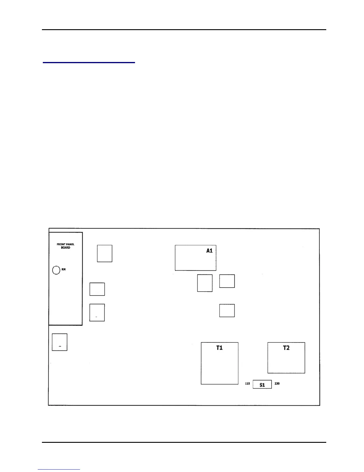
Figure 4-1, 203M Adjustment Locations