1-26
Chapter 1: Product introduction
1.8.2 Internal connectors
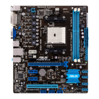
1. Power, CPU and chassis fan connectors
(3-pin PWR FAN, 4-pin CPU_FAN, and 3-pin CHA_FAN)
Connect the fan cables to the fan connectors on the motherboard, ensuring that the
black wire of each cable matches the ground pin of the connector.
DO NOT forget to connect the fan cables to the fan connectors. Insufcient air ow inside
the system may damage the motherboard components. These are not jumpers! DO NOT
place jumper caps on the fan connectors.
• The CPU_FAN connector supports a CPU fan of maximum 2A (24 W) fan power.
• Only the CPU_FAN and CHA_FAN connectors support the ASUS Fan Xpert feature.
• If you install two VGA cards, we recommend that you plug the rear chassis fan cable
to the motherboard connector labeled CHA_FAN for better thermal environment.
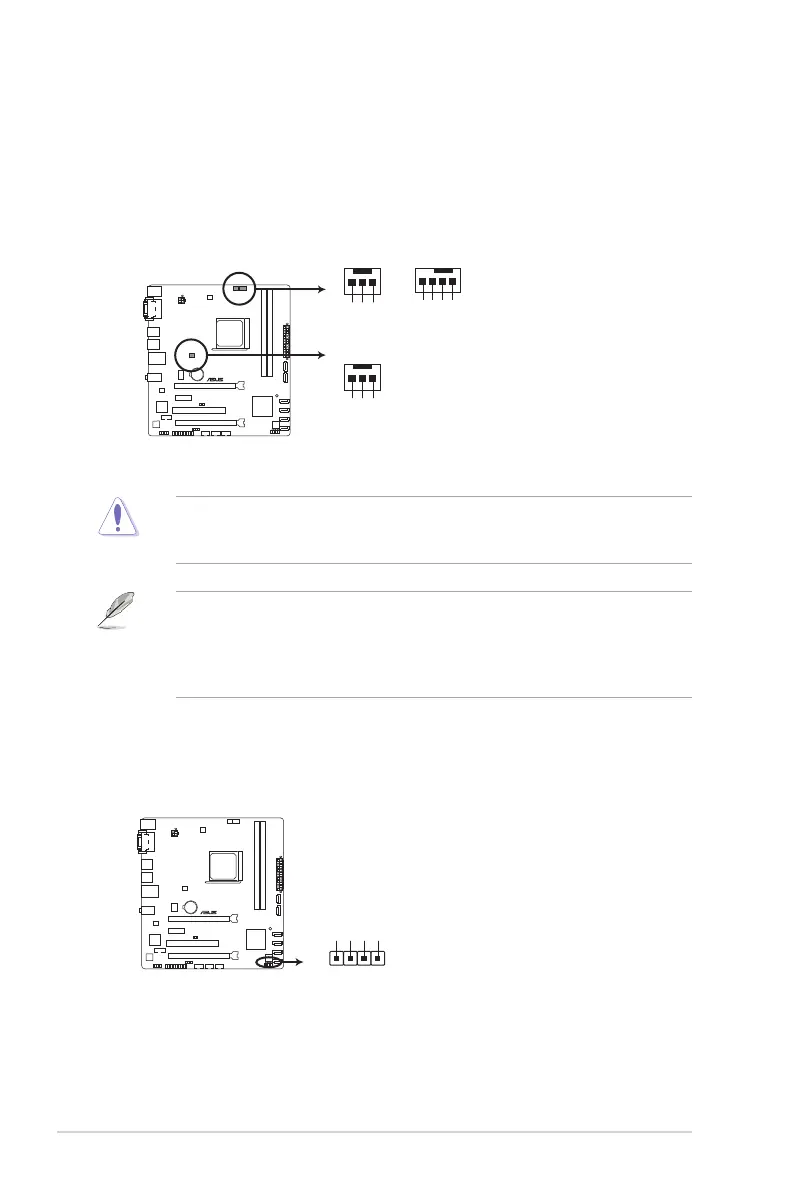
2. Speaker connector (4-pin SPEAKER)
This 4-pin connector is for the chassis-mounted system warning speaker. The speaker
allows you to hear system beeps and warnings.
F1A55-M LE R2.0
F1A55-M LE R2.0 fan connectors
CPU_FANPWR_FAN
CPU FAN PWM
CPU FAN IN
CPU FAN PWR
GND
Rotation
+12V
GND
CHA_FAN
Rotation
+12V
GND
F1A55-M LE R2.0
F1A55-M LE R2.0 Speaker connector
+5V
GND
GND
Speaker Out
SPEAKER
PIN 1

 Loading...