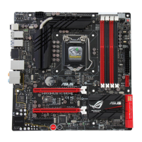
ASUS MAXIMUS VI GENE
1-7
Chapter 1
Layout contents
Connectors/Jumpers/Buttons and switches/Slots Page
1. ATX power connectors (24-pin EATXPWR; 8-pin EATX12V) 1-44
2. LGA1150 CPU Socket 1-8
3. CPU, chassis, and optional fan connectors (4-pin CPU_FAN; 4-pin
CPU_OPT; 4-pin CHA_FAN1-3)
1-43
4. DDR3 DIMM slots 1-9
5. Q_Code LEDs 1-32
6. LN2 Mode jumper (3-pin LN2_MODE) 1-29
7. MemOK! button 1-28
8. USB 3.0 connectors (20-1 pin USB3_12) 1-40
9. Intel
®
Z87 Serial ATA 6 Gb/s connectors (7-pin SATA6G_1-6 [red]) 1-39
10. ASMedia
®
Serial ATA 6 Gb/s connectors (7-pin SATA6G_E1/2 [red]) 1-40
11. System panel connector (20-8 pin PANEL) 1-45
12. DirectKey button 1-45
13. TPM connector (20-1 pin TPM) 1-47
14. DirectKey connector (2-pin DRCT) 1-46
15. USB 2.0 connectors (10-1 pin USB1112; USB1314) 1-42
16. ROG Extension connector (18-1 pin ROG_EXT) 1-47
17. RESET button 1-27
18. START (Power-on) button 1-27
19. Front panel audio connector (10-1 pin AAFP) 1-41
20. Digital audio connector (4-1 pin SPDIF_OUT) 1-41
21. mPCIe Combo II connector (36-2-pin MPCIE_COMBO_II) 1-46
 Loading...