1-8
Chapter 1: Product Introduction
Chapter 1
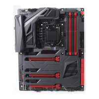
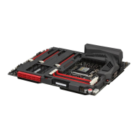
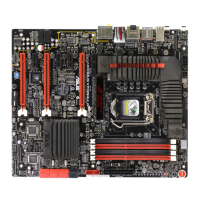
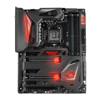
Layout contents
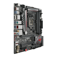
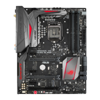
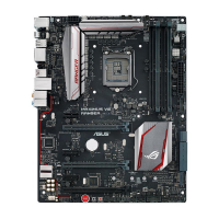
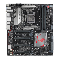
Connectors/Jumpers/Buttons and switches/Slots Page
1. ATX power connectors (24-pin EATXPWR; 8-pin EATX12V) 1-43
2. LGA1151 CPU Socket 1-9
3. CPU, water pump, CPU optional, extension, and chassis fan connectors
(4-pin CPU_FAN; 4-pin W_PUMP; 4-pin CPU_OPT; 5-pin EXT_FAN;
4-pin CHA_FAN1-4)
1-42
4. LN2 Mode jumper (3-pin LN2_MODE) 1-37
5. DDR4 DIMM slots 1-10
6. T_Sensor connector (2-pin T_SENSOR1-3) 1-45
7. Q_Code LED 1-31
8. Power-on button (START) 1-27
9. RESET button (RESET) 1-27
10. USB 3.0 connector (20-1 pin USB3_12; USB3_34) 1-39
11. Intel
®
Z170 Serial ATA 6 Gb/s connectors (7-pin SATA6G_12;
SATA6G_34)
1-38
12. ASMedia
®
Serial ATA 6 Gb/s connectors (7-pin SATA6G_E12) 1-39
13. M.2 (Socket 3) 1-47
14. U.2 connector (U.2_1) 1-47
15. System panel connector (20-5 pin PANEL) 1-44
16. USB 2.0 connectors (10-1 pin USB1314, USB1112)
1-40
17. ROG Extension connector (18-1 pin ROG_EXT) 1-45
18. MemOK! button 1-28
19. Aura Strip Header (4-pin RGB_HEADER1) 1-46
20. Front panel audio connector (10-1 pin AAFP) 1-41
21. LED connectors (LED_CON_MOS; LED_CON_CPU; LED_CON_PCH) 1-48
 Loading...