5
Deutsch
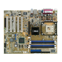
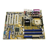
ASUS P4P800-E Deluxe-Motherboard
2. Installieren der CPU
Folgen Sie bitte den nachstehenden Schritten, um eine CPU zu installieren.
1. Suchen Sie auf dem Motherboard den 478-pol. ZIF-Sockel.
2. Heben Sie den Sockelhebel bis zu einem Winkel von 90 Grad hoch.
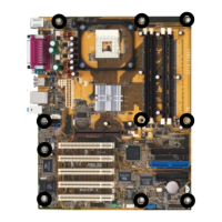
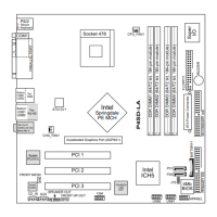
1. Motherboard layout
WARNUNG!
Die CPU passt nur in einer Richtung in den Sockel. Stecken Sie die CPU nicht
gewaltsam hinein, um verbogene Kontaktstifte und Schäden an der CPU zu
vermeiden!
PLED-
Ground
PWR
+5V
Speaker
Ground
ExtSMI#
Ground
Reset
Ground
Ground
PLED+
IDE_LED+
IDE_LED-
* Benötigt ATX-Stromversorgung.
SMI-Leiter
ATX-Stromschalter*
Strom-LED
IDE-LED
Reset-Schalter
Lautsprecher-
anschluss
PCI1
PANEL
P4P800-E
®
CR2032 3V
Lithium Cell
CMOS Power
CD
AUX
Super
I/O
4Mbit
Firmware
Hub
PS/2KBMS
T: Mouse
B: Keyboard
Below:Mic In
Center:Line Out
Top:Line In
Accelerated Graphics Port (AGP)
CPU_FAN
FP_AUDIO
Audio
Codec
USB2.0
T: USB3
B: USB4
Top:
RJ-45
GAME
Socket 478
ATX12V1
CHASSIS
DDR DIMM_B1 (64 bit,184-pin module)
PCI2
PCI3
PCI4
PCI5
IE1394_2
CLRTC
FLOPPY1
PRI_IDE1
SEC_IDE1
ATX Power Connector
DDR DIMM_A1 (64 bit,184-pin module)
DDR DIMM_A2 (64 bit,184-pin module)
DDR DIMM_B2 (64 bit,184-pin module)
KBPWR
CHA_FAN
1394
Top:
USB1
USB2
Bottom:
Intel
ICH5R
Intel
82865PE
Memory
Controller
Hub
Marvell
88E8001
Gbit
Speech
Controller
SATA1
COM2
USB_56 USB_78
PROMISE
PDC20378
SB_PWR
SMB20
PWR_FAN
SATA2
VIA
VT6307
Chipset
PRI_RAID
MODEM
WIFI
USBPW12
USBPW34
USBPW56
USBPW78
PARALLEL PORT
COM1
SPDIF_O
SPDIF_O2
Below:
Side surround L/R
Center:
Back surround L/R
Top:Bass
SATA_RAID1
SATA_RAID2
CLRTC
Normal Clear CMOS
(Default)
12 23
(Default)
+5V +5VSB
KBPWR
2312
SMB20
Disable
Enable
(Default)
3
2
21
3
2
2
1
+5V
(Default)
+5VSB
USBPW12
USBPW34
3
2
21
+5V
(Default)
+5VSB
USBPW56
USBPW78
PANEL
 Loading...