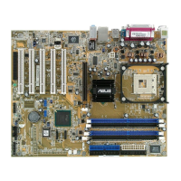
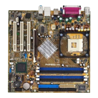
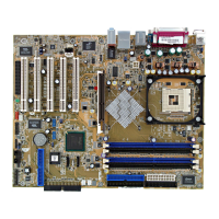
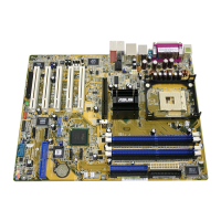
ASUS P4P800 motherboard user guide
2-23
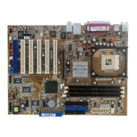
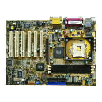
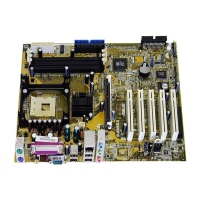
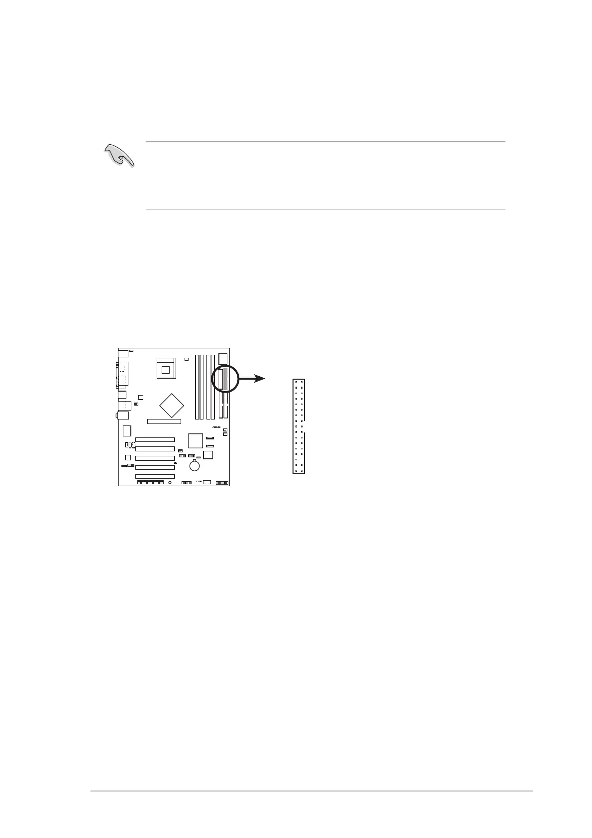
2.8 Connectors
This section describes and illustrates the internal connectors on the
motherboard.
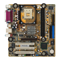
1. Floppy disk drive connector (34-1 pin FLOPPY1)
This connector supports the provided floppy drive ribbon cable. After
connecting one end to the motherboard, connect the other end to the
floppy drive. (Pin 5 is removed to prevent incorrect insertion when
using ribbon cables with pin 5 plug).
P4P800
NOTE: Orient the red markings o
the floppy ribbon cable to PIN 1.
P4P800 Floppy Disk Drive Connector
PIN 1
FLOPPY1
Always connect ribbon cables with the red stripe to Pin 1 on the
connectors. Pin 1 is usually on the side closest to the power connector
on hard drives and CD-ROM drives, but may be on the opposite side
on floppy disk drives.

 Loading...