EasyManua.ls Logo

Asus P4SP-MX User Manual

Asus P4SP-MX
64 pages
To Next Page IconTo Next Page
Page #1 background imageLoading...
Page #1 background image
Motherboard
P4SP-MX
User Guide

Other manuals for Asus P4SP-MX

Question and Answer IconNeed help?

Do you have a question about the Asus P4SP-MX and is the answer not in the manual?

Asus P4SP-MX Specifications

General IconGeneral
Form FactorMicro ATX
CPU SocketSocket 478
ChipsetSiS 651
Front Side Bus400/533 MHz
Memory Slots2 x DIMM
Max Memory2 GB
IDE2 x ATA133
SATA2 x SATA 150
Onboard AudioYes
Audio Channels6
Onboard LANYes
Power Connector20-Pin ATX
CPU TypePentium 4
Memory StandardDDR SDRAM
Expansion Slots1 x AGP, 3 x PCI
LAN ChipsetRealtek 8201BL
USB Ports4 via headers
Dimensions9.6" x 8" (24.5cm x 20.3cm)

Summary

Safety Information

Electrical Safety

Precautions to prevent electrical shock hazards during system handling and relocation.

Operation Safety

Guidelines for safe installation and use, including handling components and environmental factors.

P4SP-MX Specification Summary

Chapter 1: Product Introduction

1.3 Special Features

1.3.1 Product Highlights

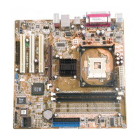
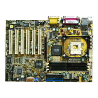
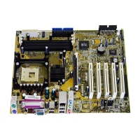
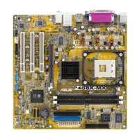
Describes the main features and specifications of the motherboard, such as CPU and chipset.

1.3.2 ASUS Unique Features

1.4 Before You Proceed

1.5 Motherboard Overview

1.5.1 Motherboard Layout

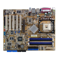
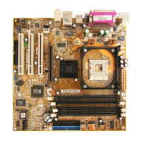
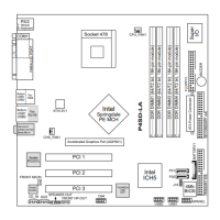
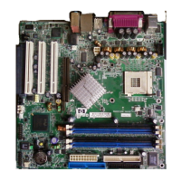
Illustrates the physical arrangement of components and connectors on the motherboard.

1.6 Central Processing Unit (CPU)

1.6.1 Overview

General information about the CPU, its socket, and installation orientation marks.

1.6.2 Installing the CPU

1.7 System Memory

1.7.3 Installing a DIMM

1.7.4 Removing a DIMM

1.8 Expansion Slots

1.8.1 Installing an Expansion Card

Step-by-step guide for physically installing an expansion card into a slot.

1.8.2 Configuring an Expansion Card

Instructions for setting up software and BIOS for installed expansion cards.

1.8.3 PCI Slots

1.8.4 AGP Slot

1.9 Jumpers

Clear RTC RAM (CLRTC1)

Instructions for clearing the CMOS RTC RAM using the CLRTC1 jumper.

USB Device Wake-Up (3-pin USBPW12, USBPW34, USBPW56)

1.10 Connectors

1.10.1 Rear Panel Connectors

Detailed explanation of each rear panel connector and its function.

1.10.2 Internal Connectors

IDE Connectors (PRI_IDE1, SEC_IDE1)

Information on connecting IDE hard disk drives using ribbon cables.

ATX Power Connectors (20-pin ATXPWR1, 4-pin ATX12V1)

Front Panel Audio Connector (10-1 pin FP_AUDIO1)

CPU and Chassis Fan Connectors (3-pin CPU_FAN1, CHA_FAN1)

USB Header (10-1 pin USB56)

Internal Audio Connectors (4-pin AUX1, CD1)

Serial Port Connector (10-1 pin COM1)

System Panel Connector (10-1 pin PANEL1)

Chapter 2: BIOS Information

2.1 Managing and Updating Your BIOS

Creating a Bootable Floppy Disk

Step-by-step guide to creating a bootable floppy disk for BIOS operations.

2.1.2 Using ASUS EZ Flash to Update the BIOS

2.1.3 Using the AFLASH Utility

Copying the Original Motherboard BIOS

Procedure to copy the original motherboard BIOS file using AFLASH.

Updating the BIOS

2.1.4 Recovering the BIOS with CrashFree BIOS

2.1.5 ASUS Update

2.2 BIOS Setup Program

2.3 Main Menu

System Time

How to set the system time in the BIOS Setup.

System Date

How to set the system date in the BIOS Setup.

2.3.1 Primary and Secondary Master/Slave

Type [Auto]

Automatic detection of IDE hard disk drive type.

[User Type HDD]

Manual configuration of IDE hard disk drive parameters.

2.3.2 Keyboard Features

2.4 Advanced Menu

CPU Speed [Manual]

Allows manual adjustment of the CPU's internal frequency.

2.4.1 Chip Configuration

SDRAM Configuration [By SPD]

Sets optimal SDRAM timings based on SPD information.

2.4.2 I/O Device Configuration

2.4.3 PCI Configuration

Onboard PCI Devices Control

2.5 Power Menu

Power Management [User Defined]

Activates or deactivates automatic power saving features.

2.5.1 Power Up Control

2.5.2 Hardware Monitor

2.6 Boot Menu

Boot Sequence

Defines the order of devices the system checks for bootable media.

2.7 Exit Menu

Exit & Save Changes

Exits Setup after saving all modified settings to CMOS.

Exit & Discard Changes

Exits Setup without saving any changes made.

Load Setup Defaults

Loads default parameter values for all BIOS settings.

Chapter 3: Software Support

3.1 Install an Operating System

3.2 Support CD Information

3.2.2 Installation Items

Related product manuals