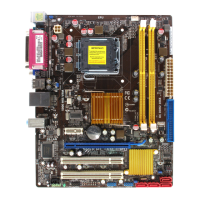
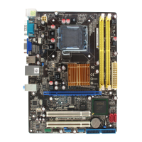
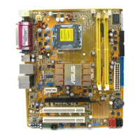
ASUS P5KPL-CM 1-9
To prevent damage to the socket
pins, do not remove the PnP cap
unless you are installing a CPU.
2. Press the load lever with your
thumb (A), then move it to the left
(B) until it is released from the
retention tab.
A
B
Load lever
Retention tab
3. Lift the load lever in the direction of
the arrow to a 135º angle.
4. Lift the load plate with your thumb
and forenger to a 100º angle (4A),
then push the PnP cap from the
load plate window to remove (4B).
Load plate
PnP cap
4A
4B
3
5. Position the CPU over the socket,
making sure that the gold triangle
is on the bottom-left corner of the
socket then t the socket alignment
key into the CPU notch.
Gold
triangle
mark
Alignment key
CPU notch
The CPU ts in only one correct
orientation. DO NOT force the
CPU into the socket to prevent
bending the connectors on the
socket and damaging the CPU!
 Loading...