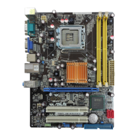
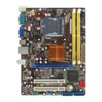
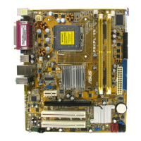
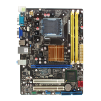
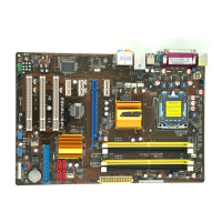
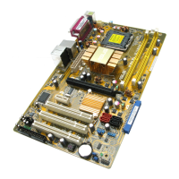
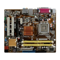
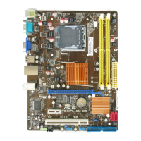
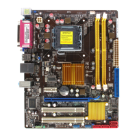
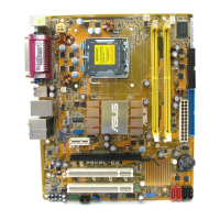
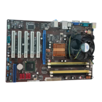
ASUS P5KPL IPC/SI 1-13
3. IDE connector (40-1 pin PRI_IDE)
The onboard IDE connector is for the Ultra DMA 100/66/33 signal cable. There are
three connectors on each Ultra DMA 100/66/33 signal cable: blue, black, and gray.
Connect the blue connector to the motherboard’s IDE connector, then select one of the
following modes to congure your device.
Drive jumper setting Mode of device(s) Cable connector
Single device Cable-Select or Master - Black
Two devices
Cable-Select
Master Black
Slave Gray
Master Master
Black or gray
Slave Slave
• Pin 20 on the IDE connector is removed to match the covered hole on the Ultra DMA
cable connector. This prevents incorrect insertion when you connect the IDE cable.
• Use the 80-conductor IDE cable for Ultra DMA 100/66/33 IDE devices.
If any device jumper is set as “Cable-Select,” ensure that all other device jumpers have the
same setting.
4. Serial port connector (10-1 pin COM2)
The connector is for a serial (COM) port. Connect the serial port module cable to the
connector, then install the module to a slot opening at the back of the system chassis.
The serial port bracket (COM2) is purchased separately.
 Loading...