1-13 Chapter 1: Product introduction
• These connectors are set to [IDE Mode] by default. In IDE mode, you can connect Serial
ATA boot/data hard disk drives to these connectors. If you intend to create a Serial ATA
RAID set using these connectors, set the SATA Mode item in the BIOS to [RAID Mode].
See section 2.5.4 SATA Conguration for details.
• Before creating a RAID set, refer to the RAID Supplementary Guide included in the
folder named Manual in the support DVD.
• You must install Windows
®
XP Service Pack 3 or later version before using Serial ATA
hard disk drives. The Serial ATA RAID feature (RAID 0, 1, 5, and 10) is available only if
you are using Windows
®
XP SP3 or later version.
• When using hot-plug and NCQ, set the SATA Mode item in the BIOS to [AHCI Mode].
See section 2.5.4 SATA Conguration for details.
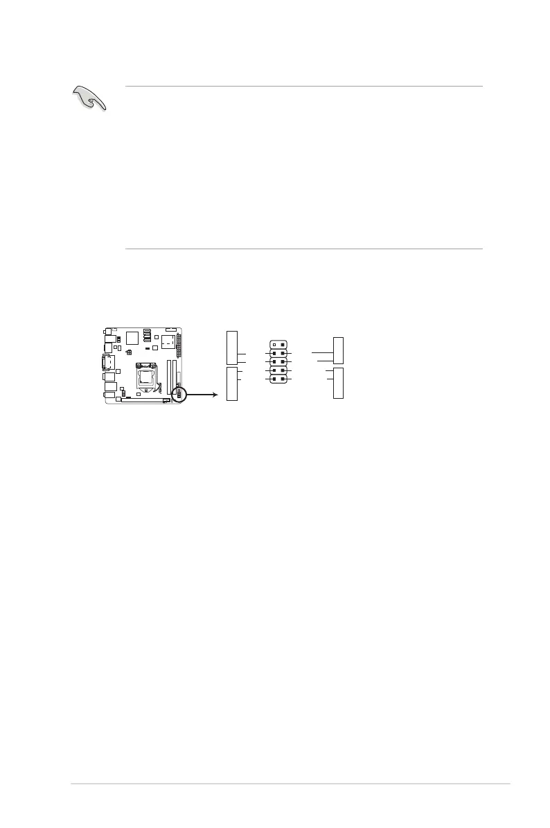
6. System panel connector (10-1 pin F_PANEL)
This connector supports several chassis-mounted functions.
• System power LED (2-pin PLED)
This 2-pin connector is for the system power LED. Connect the chassis power LED
cable to this connector. The system power LED lights up when you turn on the system
power, and blinks when the system is in sleep mode.
• Hard disk drive activity LED (2-pin +HDLED)
This 2-pin connector is for the HDD Activity LED. Connect the HDD Activity LED cable
to this connector. The IDE LED lights up or ashes when data is read from or written to
the HDD.
• Power/Soft-off button (2-pin PWRBTN)
This 2-pin connector is for the system power button.
• Reset button (2-pin RESET)
This 2-pin connector is for the chassis-mounted reset button for system reboot without
turning off the system power.
P8H67-I DELUXE
P8H67-I DELUXE System panel connector
PIN 1
PWRBTN
GND
PWR
PLED-
PLED+
Reset
Ground
HD_LED-
HD_LED+
F_PANEL
PLED
+HDLED RESET
 Loading...